
Setup: Netgear ProSafe AC Access Point WAC740 User Manual
Content
NETGEAR ProSAFE Dual Band Wireless Access Point Mode WAC740
Introduction
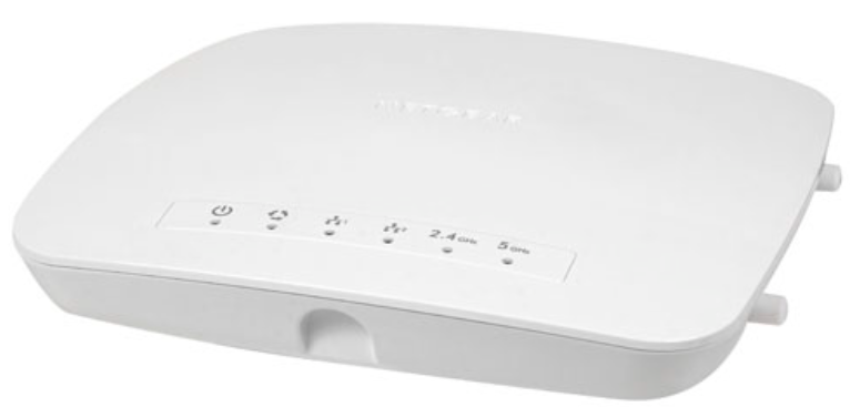
The Netgear ProSafe AC Access Point WAC740 is a high-performance wireless access point designed to meet the demands of modern businesses and organizations. Launched in 2015, this device is part of Netgear's ProSafe series, known for its reliability and robust features. The WAC740 is intended for use in medium to large-sized enterprises, providing strong and reliable Wi-Fi coverage. It supports the latest 802.11ac standard, offering speeds up to 1.9 Gbps. The estimated price of the Netgear ProSafe AC Access Point WAC740 is around $500, making it a competitive option in the market for business-grade Wi-Fi solutions.
Overview
Model WAC740 is intended as a controller-managed access point for centralized management with a NETGEAR wireless controller from small (WC7500) to mid-size (WC7600) and large (WC9500) deployments. The access point operates with Multi-user MIMO (MU-MIMO), provides concurrent operation in the 2.4 GHz and 5 GHz radio bands, and can achieve speeds up to 600 Mbps for 2.4 GHz networks and up to 1.7 Gbps for 5 GHz networks.
The access point provides one Power over Ethernet plus (PoE+) port (LAN port 1) that can support up to 2.5 Gbps of throughput, enabling a single connection to a 2.5 Gbps–capable switch such as the NETGEAR M4200 Series ProSAFE Managed Switch.
The second LAN port (LAN port 2) is intended for a LAG configuration, which enables the throughput to exceed 1 Gbps even if a 2.5 Gbps–capable switch is not present on the other end.
Note: Because model WAC740 is not intended as a standalone access point, NETGEAR does not provide a separate user manual for this access point. You must configure the access point through a NETGEAR wireless controller. For information about configuring the access point, see the ProSAFE Wireless Controller Models WC7500, WC7600, WC7600v2, and WC9500 User Manual, which you can download by visiting downloadcenter.netgear.com.
Unpack Your Access Point
Your package contains the following items:
- Dual Band Wireless AC Access Point Model WAC740
- Category 5e Ethernet cable
- Installation guide
- Ceiling and wall installation kit
- Ceiling and wall installation guide
- Note: A power adapter is not included in the package. A power adapter is required if you do not provide PoE+ power to the access point.
- Contact your reseller or customer support in your area if any parts are missing or damaged. Visit the NETGEAR website at netgear.com/support/contact.aspx for the telephone number of customer support in your area.
Hardware Description
The following sections describe the top and rear hardware functions of the access point.
- Top Panel on page 7
- Rear Panel on page 9
- Product Label on page 10
Top Panel
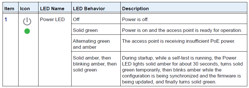
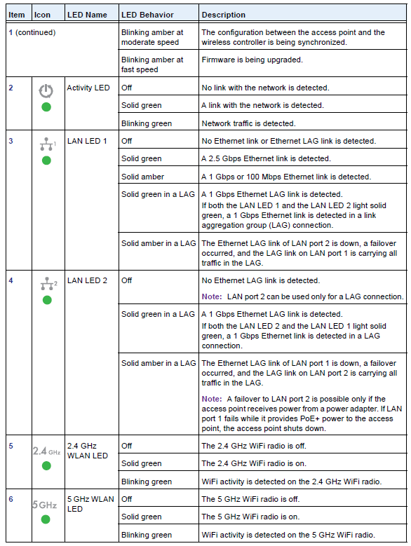
The LEDs of the access point are described in the following figure and table:
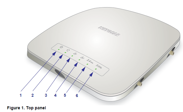
Table 1. Top panel LEDs
Rear Panel
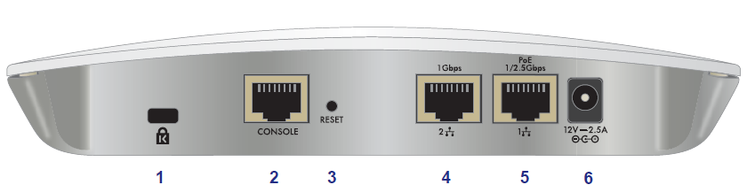
The rear panel components of the access point, from left to right, are described in the following list:
- Cable security lock. Receptacle for an optional lock.
- Console port. Lets you connect the access point to an optional console terminal. The port provides an RJ-45 connector and supports the following settings: 115200 K default baud rate, 8 data bits, no (N) parity bit, and
- one (1) stop bit 3. Factory default Reset button. Using a sharp object, press and hold this button for about ten seconds to reset the access point to factory default settings. All configuration settings are lost, and the default password is restored. For more information, see Factory Default Settings on page 36.
- LAN port 2. 10/100/1000BASE-T Gigabit Ethernet (RJ-45) port with Auto Uplink (Auto MDI-X) for a static link aggregation group (LAG) connection to a switch.
- LAN port 1. 100/1000/2500BASE-T Gigabit Ethernet (RJ-45) port with Auto Uplink (Auto MDI-X) and support for IEEE 802.3at PoE+ for connection to a switch or router that can provide PoE+. LAN port 1 is intended for the normal connection to a switch.
- DC power socket. Socket for an optional 12 VDC, 2.5A power adapter. A power adapter is not included in the package. A power adapter is required if you do not provide PoE+ power to the access point.
Side Panels
- External multiple-input, multiple-output (MIMO) antennas can extend the WiFi signal range indoors or in fringe network areas. The access point can support up to four optional 2.4 GHz or 5 GHz dual-band antennas.
- External antennas plug into the reverse SMA antenna connectors on the side panels of the access point. Each side panel provides two antenna connectors for a total of four antenna connectors. For information about optional NETGEAR antennas, visit netgear.com/business/products/wireless/accessories.
Product Label
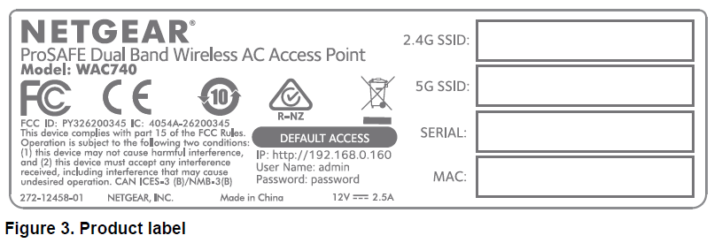
The product label on the bottom of the enclosure displays the access point’s default WiFi network names (SSIDs), serial number, MAC address, default login information (IP address, user name, and password), regulatory compliance, and other information.
Documentation Resources
For more information about the WAC740 access point, see the following documents, which you can download by visiting downloadcenter.netgear.com:
- NETGEAR ProSAFE Dual Band Wireless AC Access Point WAC740 Installation Guide
- NETGEAR ProSAFE Dual-Band Wireless AC Access Points WAC720, WAC730, and WAC740 Ceiling and Wall Installation Guide
- ProSAFE Wireless Controller Models WC7500, WC7600, WC7600v2, and WC9500 User Manual
You can also visit netgear.com/business/products/wireless/business-wireless, where you can find the data sheet for model WAC740 and other information.
Note: Because model WAC740 is not intended as a standalone access point, NETGEAR does not provide a separate user manual for this access point.
Installation
Step 1: Consider the System Requirements
Before installing the access point, make sure that your network includes the following components:
- An NBASE-T or 10/100/1000BASE-T PoE+ (802.3at) switch.
- Note: The access point requires PoE+. PoE (802.3af) is not sufficient.
- If the switch does not provide PoE+, a NETGEAR power adapter for the access point and an AC power source are required.
- A NETGEAR wireless controller in the same Layer 2 or Layer 3 network as the access point.
- If the network does not include a DHCP server, a computer with a static IP address of 192.168.0.210 and a subnet mask of 255.255.255.0 is required so that you can connect to the access point at its default IP address of 192.168.0.160 and configure the appropriate IP address for your network.
Step 2: Consider the WiFi Equipment Placement and Range Guidelines
The range of your WiFi connection can vary significantly based on the location of the access point. The latency, data throughput performance, and power consumption of WiFi devices also vary depending on your configuration choices. In addition, the time it takes to establish a WiFi connection can vary depending on both your security settings and placement.
Note: Failure to follow these guidelines can result in significant performance degradation or inability to connect over WiFi to the access point. For complete performance specifications, see Appendix B, Supplemental Information.
For best results, place your access point according to the following general guidelines:
- Near the center of the area in which the WiFi devices will operate.
- In an elevated location , such as a high shelf, where the WiFi devices are in within a line of sight (even if through walls).
- Away from possible sources of interference,, such as the following:
- Ceiling fans- Home security systems
- Microwaves
- Computers
- Base of a cordless phone
- 2.4 GHz cordless phone
- 5 GHz cordless phone
- Away from large metal surfaces, large glass surfaces, insulated walls, and items such as the following:
- Brick walls or surfaces
- Concrete walls or surfaces
- Solid metal doors
- Aluminum studs
- Fish tanks
- Mirrors
- Placing an external antenna in a vertical position provides the best side-to-side coverage. Placing an external antenna in a horizontal position provides the best up-and-down coverage. (An external antenna does not come standard with the access point.)
Step 3: Connect the Access Point to Your Network
Connecting the access point to the network involves the following tasks:
- Configure the network IP address of the access point. The access point uses a DHCP client that is enabled by default. If your network includes a DHCP server, the access point obtains an IP address from the DHCP server. If your network does not include a DHCP server, the access point sets its IP address to a static IP address of 192.168.0.160. In that situation, you must use a computer to connect to the access point so that you can configure the network IP address of the access point (see Step 3a: If the Network Does Not Include a DHCP Server, Connect the Access Point to a Computer on page 17).
If your network does include a DHCP server, note the following:- Make sure that Option 43 is enabled on the DHCP server.
- Make sure that the DHCP server specifies the IP address of the NETGEAR wireless controller that you intend to use to discover and configure the access point.
- We recommend that you reserve an IP address for the access point on the DHCP server.
- Connect the access point to a switch. In a typical setup, you connect the access point to a switch that is connected to the same Layer 2 or Layer 3 network as the wireless controller. You can set up a single 100/1000 Mbps or 2.5 Gbps Ethernet connection to the switch, or you can set up a LAG connection to the switch (see Step 3b: Connect the Access Point to a Switch on page 18).
- Provide power to the access point. Either the switch to which you connect the access point provides PoE+ power to the access point,t or you must use a power adapter to provide power to the access point (see Step 3c: Provide Power to the Access Point on page 19).
Step 3a: If the Network Does Not Include a DHCP Server,
Connect the Access Point to a Computer
If your network does not include a DHCP server, you must connect a computer to the access point to configure the network IP address of the access point. You also must know the IP address of the wireless controller in the network.
Note: If the access point was previously connected to a network with a DHCP server, the access point retains the IP address that it received from the DHCP server. In such a situation, before you start the following procedure, first reset the access point to factory default settings (see Factory Default Settings on page 36); otherwise, you cannot connect to the access point by using its default IP address.
To configure the access point’s IP address settings and other information:
- Configure a computer with a static IP address of 192.168.0.210 and a subnet mask of 255.255.255.0.
- Use an Ethernet cable to connect LAN port 1 on the access point to an Ethernet port on your computer.
- In the address bar of a web browser, enter the IP address of the access point.
- The default IP address is 192.168.0.160.
- A login window displays.
- Enter the user name and password . The user name is admin. The default password is password. The user name and password are case-sensitive.
The Network Settings page displays. (The full path is Configuration > System > Network Settings.) - In the IP Settings section, select the DHCP client disable radio button.
- By default, the Enable DHCP Client radio button is selected, and the access point functions as a DHCP client.
- In the IP Settings section, configure the IP address information for the access point in the network.
- In the Controller Settings section, configure the IP address for the wireless controller in the network.
- If you must change the management VLAN settings, do so in the VLAN Settings section. By default, VLAN 1 is the management VLAN, and it is untagged.
- Click the Apply button . Your settings are saved.
- Log out of the access point and disconnect the access point from the computer.
- Reconfigure the computer that you used for this process back to its original TCP/IP settings.
Step 3b: Connect the Access Point to a Switch
You can set up a single 100/1000 Mbps or 2.5 Gbps Ethernet connection to the switch , or you can set up a LAG connection to the switch. For more information about these options, see Chapter 2, Connections for Multi-Gigabit Ethernet Throughput.
Option 1: Set Up a 100/1000 Mbps or 2.5 Gbps Connection to the Switch
For more information about this type of setup, see Connection to a High-Speed Switch on page 12.
To set up a 100/1000 Mbps or 2.5 Gbps connection to the switch:
- Connect one end of a Category 5e (Cat 5e) cable (included with the access point) to the access point LAN port 1 (the rightmost LAN port).
LAN port 1 on the access point can provide a speed of up to 2.5 Gbps. If the switch provides a 2.5 Gbps (or faster) connection, you could use a higher-rated Ethernet cable (Cat 6, Cat 6a, or Cat 7). - Connect the other end of the Ethernet cable to a port on the switch.
Option 2: Set Up a LAG Connection to a Switch
For more information about this type of setup, see Static LAG Connection to a Switch on page 13.
To set up a LAG between the access point and the switch:
- Connect one end of a Category 5e (Cat 5e) cable (included with the access point) to the access point LAN port 1 (the rightmost LAN port).
- Connect the other end of the Ethernet cable to a port on the switch.
- Connect one end of another (Cat 5e) cable (not included with the access point) to the access point LAN port 2. LAN port 2 on the access point can be used only for a LAG connection.
- Connect the other end of the Ethernet cable to a port on the switch.
- On the switch, configure a static LAG for the access point.
For more information, see the documentation for your switch. If you use a NETGEAR M4200 ProSAFE Managed Switch, see the M4200 and M4300 Series ProSAFE Managed Switches Web Management User Manual, which you can download by visiting downloadcenter.netgear.com.
Note: For the LAG to function, you must also enable link aggregation on the access point itself and configure link aggregation for the access point on the wireless controller. For information about these configurations, see the ProSAFE Wireless Controller Models WC7500, WC7600, WC7600v2, and WC9500 User Manual, which you can download by visiting downloadcenter.netgear.com.
Step 3c: Provide Power to the Access Point
If the switch provides PoE+ power, no further action is required to power the access point. If the switch does not provide PoE+, you must connect the access point to a power adapter.
Option 1: The Access Point Receives Power From a PoE+ Switch
The access point requires PoE+ power according to IEEE 802.3at, with 42 VDC–57 VDC, 600mA. PoE, according to IEEE 802.3af, is not sufficient for the access point.
CAUTION: PoE might be considered a network environment 0 per IEC TR 62101, and thus the interconnected ITE circuits might be considered safety extra low voltage (SELV).
The access point does not provide an on/off power button. If the switch to which you connect the access point provides PoE+ power, the PoE+ Ethernet connection to the switch controls the power.
Option 2: Connect the Access Point to a Power Adapter
If your switch does not provide PoE+, obtain a 12 VDC, 2.5A power adapter from NETGEAR. This power adapter is specific to the WAC740 access point. Do not use another power adapter.
The access point does not provide an on/off power button. The power adapter connection controls the power.
To apply power to the access point through a power adapter:
- Connect the power adapter plug to the DC power socket on the access point.
- Plug the power adapter into a power source such as a wall socket or power strip.
Select an AC outlet that is not controlled by a wall switch, which could turn off power to the access point.
When you apply power, the Power LED on the access point’s front panel lights.
If the Power LED does not light, check to make sure that the power adapter is plugged in correctly and that the power source is functioning. If this does not resolve the problem, see Appendix A, Troubleshooting.
Step 4: Use the Wireless Controller to Discover and Configure the Access Point
The WAC740 access point is not intended as a standalone access point. You must let a NETGEAR wireless controller discover the access point, after which you can configure and manage the access point through the wireless controller. The access point must function in the same Layer 2 or Layer 3 network as the wireless controller.
For more information, see the ProSAFE Wireless Controller Models WC7500, WC7600, WC7600v2, and WC9500 User Manual, which you can download by visiting downloadcenter.netgear.com.
Note: If you are using multiple access points, it is better if adjacent access points use different radio frequency channels to reduce interference. The recommended channel spacing between adjacent access points is five channels (for example, use Channels 1 and 6, or 6 and 11, or 1 and 11).
Step 5: Test WiFi Connectivity to the Access Point
After you configure the access point through the wireless controller, make sure that WiFi devices can connect to the access point before you position and mount the access point at its permanent position.
We recommend that you configure WiFi security and other WiFi features before you deploy the access point in your network.
To test for WiFi connectivity:
- Configure your WiFi devices so that they can connect to a WiFi network that you configured on the access point.
- Verify that your WiFi devices acquired a WiFi link to the access point.
- Verify network connectivity by using a browser to connect to the Internet, or check for file and printer access on your network.
Note: If you cannot connect WiFi devices to the access point, see Appendix A, Troubleshooting.
Optional Step 6: Mount the Access Point
We recommend that you review the information in Step 2: Consider the WiFi Equipment Placement and Range Guidelines on page 15 before you mount the access point at its permanent position. The following sections explain how to mount your access point:
- Package Content of the Ceiling and Wall Installation Kit on page 21
- Drop Ceiling Installation on page 21
- Wall Installation on page 24
Package Content of the Ceiling and Wall Installation Kit
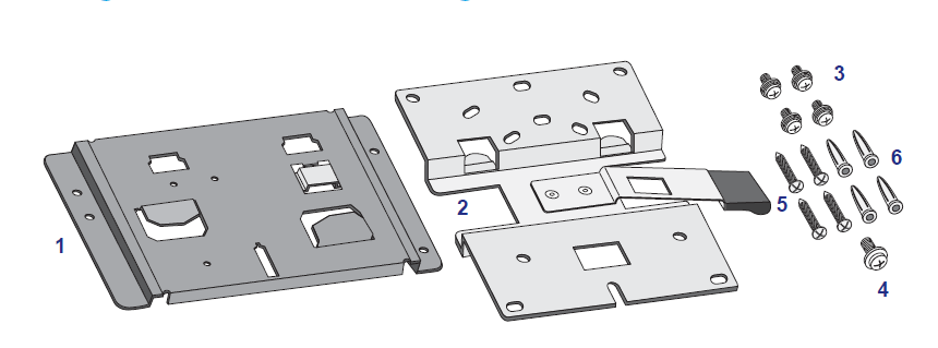
Figure 6. Ceiling and wall installation kit
The ceiling and wall installation kit contains the following components:
- One access point–mounting bracket
- One wall-mounting bracket 3. Four mounting screws with integrated washers for the access point–mounting bracket
- One T-bar screw for the access point–mounting bracket
- Four wall screws for the wall-mounting bracket
- Four wall anchors for the wall-mounting bracket
Drop Ceiling Installation
The best location for ceiling installation is at the center of your WiFi coverage area, and within line of sight of all mobile devices. Make sure that the top (the dome side) of the access point is directed toward the users and not the ceiling.
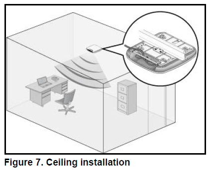
Before mounting the access point in a high location, first set up and test the access point to verify the WiFi network connectivity.
If you are mounting the access point on a hard ceiling, use the wall installation instructions.
Note: Do not place the access point in a false ceiling space facing up.
To mount your access point to a drop ceiling:
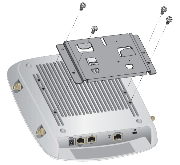
Attach the access point–mounting bracket to the access point using the four mounting screws.
Place the access point so that the ceiling rail is between the two tabs on the access point–mounting bracket.
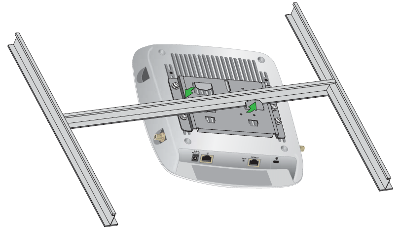
Twist the access point to hang it from the ceiling rail.
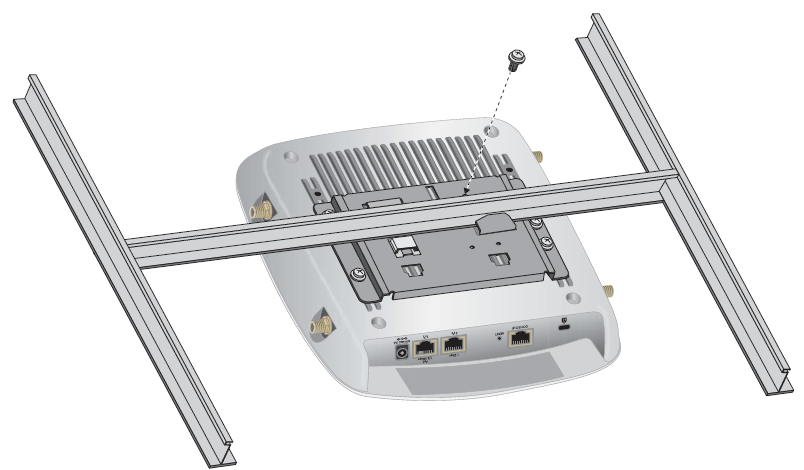
- Secure the access point to the ceiling rail using the T-bar screw.
Wall Installation
The best location for a wall installation is at the center of your WiFi coverage area, and within line of sight of all mobile devices. Make sure that the top (the dome side) of the access point is directed toward the users and not the wall.
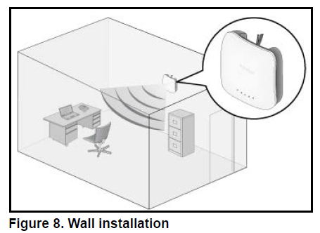
To mount your access point to a wall:
- Place the wall-mounting bracket on the wall where you want to mount the access point.
- Mark the wall where the two mounting holes are (see the figure in Step 5).
Attach the access point–mounting bracket to the access point using the four mounting screws as shown.
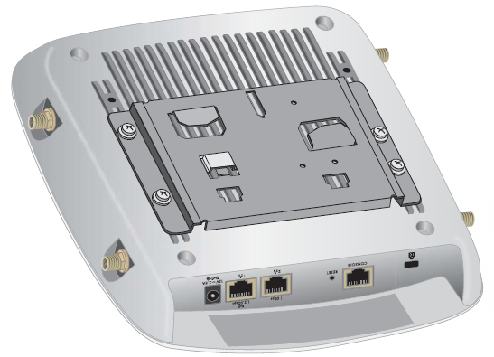
So that you can see how the brackets fit together, attach the wall-mounting bracket to the access point–mounting bracket as shown in the following figure.
The three hooks on the wall-mounting bracket fit into the three holes on the access point–mounting bracket. The handle on the wall-mounting bracket also fits into a hole on the access point–mounting bracket. Release the wall-mounting bracket by moving the handle.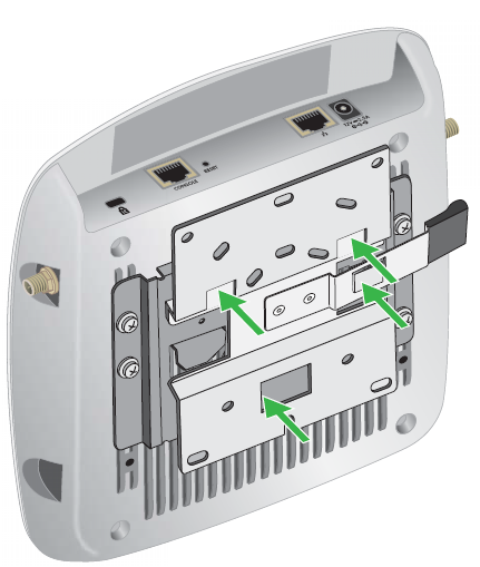
Using the wall anchors and screws, attach the wall-mounting bracket to the wall where you previously marked.
The following figures show a side view of the wall. The left figure includes a schematic view of the wall-mounting bracket .Note: Although the product package includes four wall anchors and screws,
Note: Although the product package includes four wall anchors and screws, two screws are sufficient to attach the wall-mounting bracket as shown in the previous figure. However, if you prefer, you can use four screws and insert them through the mounting holes in the corners of the wall-mounting bracket.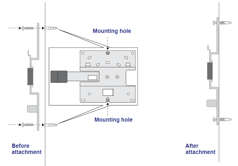
Align the three holes on the access point bracket with the three hooks on the wall-mounting bracket, and slide the access point down until it clicks and attaches to the wall-mounting bracket and is secured.
The following figures show a side view of the wall.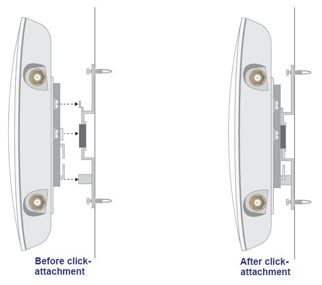
Troubleshooting
IMPORTANT: For information about access point discovery or connection problems with the wireless controller and information about using the diagnostic tools of the wireless controller, see the
“Troubleshooting and Diagnostics” chapter in the ProSAFE Wireless Controller Models WC7500, WC7600, WC7600v2, and WC9500 User Manual, which you can download by visiting downloadcenter.netgear.com.
The troubleshooting following table provides some tips for correcting simple problems that you might encounter.
Table 2. Troubleshooting chart
Troubleshoot the Basic Functions
The following sections describe how you can troubleshoot the basic functions of the access point:
- Verify the Correct Sequence of Events at Startup on page 29
- The Power LED Remains Solid Amber or Remains Blinking Amber on page 29
- No LEDs Are Lit on the Access Point on page 30
- The Activity LED, LAN LED 1, or Both LAN LEDs Are Not Lit on page 30
- The WLAN LEDs Do Not Light on page 31
- For descriptions of the LEDs, see Top Panel on page 7.
Verify the Correct Sequence of Events at Startup
If the access point is managed by a wireless controller, after you provide power to the access point, check that the following sequence of events occurs:
- The Power LED lights solid amber, and all other LED lights are solid green. If devices are connected to the LAN ports, the LAN LEDs might blink green.
- After about 30 seconds, all LEDs turn solid green. The Power LED lights green only temporarily.
- The Power LED blinks amber while the configuration between the access point and the wireless controller is being synchronized, and if firmware is being upgraded. When the synchronization and upgrade are complete, the Power LED turns solid green permanently.
- The Activity LED is lit or blinks green when Ethernet traffic is detected.
- The LAN LEDs indicate the LAN speed:
- LAN LED1. Green for a 2.5 Gbps link or amber for a 1 Gbps or 100 Mbps link.
- LAN LED 1 in a LAG. Green for a 1 Gbps LAG link.
- LAN LED 2 in a LAG. Green for a 1 Gbps LAG link. (The LAN LED 2 is active only in a LAG connection.)
- The WLAN LED is lit or blinks green when the WiFi traffic is detected.
- If any of these conditions do not occur, see the appropriate following section.
The Power LED Remains Solid Amber or Remains Blinking Amber
When the access point starts while it is controller-managed, the Power LED lights solid amber while the access point performs a self-test. After about 30 seconds, the Power LED turns solid green temporarily. The Power LED blinks amber while the configuration between the access point and the wireless controller is being synchronized, and if firmware is being upgraded. When the synchronization and upgrade are complete, the Power LED turns solid green permanently.
If the Power LED remains solid amber and does not turn green, it might indicate a system fault. If you suspect a system fault, contact NETGEAR technical support.
During the following situations, the Power LED is blinking amber:
- Synchronization. While the configuration between the access point and the wireless controller is being synchronized, the Power LED is blinking amber at a moderate speed. After two to five minutes, when the synchronization is complete, the Power LED turns solid green. The synchronization process might be followed by a firmware upgrade.
- Firmware upgrade. While firmware is being upgraded on the access point, the Power LED is blinking amber at a fast speed. After two to five minutes, when the upgrade is complete, the Power LED turns solid green.
- If the Power LED does not stop blinking amber while you suspect that the configuration or firmware upgrade is complete, wait another five minutes, and then check to see if the Power LED stops blinking amber. If the Power LED still does not stop blinking amber while the access point is controller-managed, it might indicate a system fault. If you suspect a system fault, contact NETGEAR technical support.
No LEDs Are Lit on the Access Point
When you apply power to the access point, it takes about two seconds for the Power LED to light. Wait a minute and check the Power LED status on the access point. If the access point is not receiving power, do the following:
- If you use a PoE+ switch to provide power to the access point, check these items:
- Make sure that the Ethernet cable between the access point and the PoE+ switch is correctly connected at both ends.
- Make sure that the power cord of the PoE+ switch is plugged into a working power outlet or power strip.
- Make sure that the PoE+ switch is functioning normally.
- If you use a power cord to provide power to the access point, check these items:
- Make sure that the power adapter is connected to the access point.
- Make sure that the power adapter is connected to a functioning power outlet. If it is in a power strip, make sure that the power strip is turned on. If it is plugged directly into the wall, verify that the outlet is not switched.
- Make sure that you are using the correct NETGEAR power adapter that is intended for your access point.
The Activity LED, LAN LED 1, or Both LAN LEDs Are Not Lit
If you use a single connection to a switch, the LAN LED 1 is lit. If you use a LAG connection to a switch, both LAN LEDs are lit. If the switch is connected to the network, the Activity LED is lit.
If this behavior does not occur, or if the Activity LED is not lit, a hardware connection problem has occurred. Check these items:
- Make sure that the cable connectors are securely plugged in at the access point and the (PoE+) switch.
- Make sure that the (PoE+) switch is turned on.
- Make sure that the correct cable is used. Use a standard Category 5e or Category 6 Ethernet patch cable.
The WLAN LEDs Do Not Light
The access point’s antenna is not working. Check these items:
- If the WLAN LEDs remain off, either disconnect the cable to the (PoE+) switch and then reconnect it again, or disconnect the adapter from its power source and then plug it in again.
- Make sure that the optional external antennas are tightly connected to the access point. Contact NETGEAR technical support if the WLAN LEDs remain off.
You cannot access the Internet from a WiFi Device.
A configuration problem occurred. Check these items:
- Maybe you did not restart the WiFi-enabled computer or mobile device to allow TCP/IP changes to take effect. If you did not, restart the computer or device.
- The WiFi-enabled computer or WiFi mobile might not be configured with the correct TCP/IP settings to communicate with the network. Restart the computer or device and check that TCP/IP is set up correctly for that network. For Windows computers, the usual setting is to obtain an IP address automatically.
- Make sure that you are using the correct SSID, network authentication, and data encryption settings on the WiFi-enabled computer or mobile device. These settings must be the same as the settings that are configured on the access point.
- Ping the IP address of the access point to verify that a WiFi connection exists between the WiFi-enabled computer or mobile device and the access point. If the ping fails, check the network configuration for the access point.
- Ping the default gateway to verify that a path exists from the WiFi-enabled computer or mobile device to the default gateway. If the ping fails, check the network configuration for the access point.
For information about checking the network configuration for the access point, see the ProSAFE Wireless Controller Models WC7500, WC7600, WC7600v2, and WC9500 User Manual, which you can download by visiting downloadcenter.netgear.com.
You cannot access the Access Point from a Browser.
If your network does not include a DHCP server, you must use a computer to access the access point so that you can configure the appropriate IP address for your network.
Check these items:
- The access point is correctly installed, it is powered on, and LAN connections are good. Check to see that the Activity LED and the LAN 1 LED are lit (or for a LAG connection, both LAN LEDs are lit) to verify that the Ethernet connection is good.
- If your computer uses a static IP address, make sure that it is using an IP address in the range of the access point. Configure the computer with a static IP address of 192.168.0.2100 and a subnet mask of 255.255.255.0. The access point’s default IP address is 192.168.0.160, and its subnet mask is 255.255.255.0. Make sure that your network configuration settings are correct.
- Make sure that Java, JavaScript, or ActiveX is enabled in your browser. If you are using Internet Explorer, click the Refresh button to be sure that the Java applet is loaded.
- Try quitting the browser, clearing the cache, deleting the cookies, and launching the browser again.
- Make sure that you are using the correct login information. The factory default login name is admin, and the password is password. Make sure that Caps Lock is off when entering this information.
- If the access point does not save changes that you made in the web management interface, check the following:
- When entering configuration settings, be sure to click the Apply button before moving to another page or tab, or your changes are lost.
- Click the Refresh or Reload button in the web browser. It is possible that the changes occurred, but the web browser is caching the old configuration.
Test the LAN Path to the Access Point Using the Ping Utility
Most TCP/IP terminal devices and routers contain a ping utility that sends an echo request packet to the designated device. The device then responds with an echo reply. You can easily troubleshoot a TCP/IP network by using the ping utility on your computer, as described in the following procedure.
You can ping the access point from a computer that is connected to the same network as the access point to verify that the LAN path to your access point is set up correctly.
To ping the access point from a computer running Windows:
- From the Windows toolbar, click the Start button, and select Run.
- In the field provided, type ping followed by the IP address of the access point, as in this example: ping 192.168.0.100
- Click the OK button.
A message like the following one displays:
Pinging <IP address> with 32 bytes of data
If the path is working, you see this message:
Reply from < IP address >: bytes=32 time=NN ms TTL=xxx
If the path is not working, you see this message:
Request timed out - If the path is not functioning correctly, one of the following problems could be occurring:
- Wrong physical connection:- Make sure that the Activity LED and the LAN LED 1 are lit. If one or both of these LEDs are off, follow the instructions in The Activity LED, LAN LED 1, or Both LAN LEDs Are Not Lit on page 30.
- Check to see that the corresponding link LEDs are lit for your network interface card and for the hub ports (if any) that are connected to your workstation and access point.
- Wrong network configuration:
- Verify that the Ethernet card driver software and TCP/IP software are both installed and configured on your computer.
- Verify that the IP address for your access point and your computer are correct and that the addresses are on the same subnet.
Technical Specifications
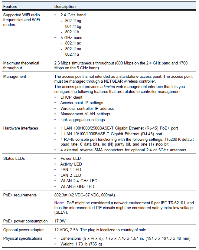
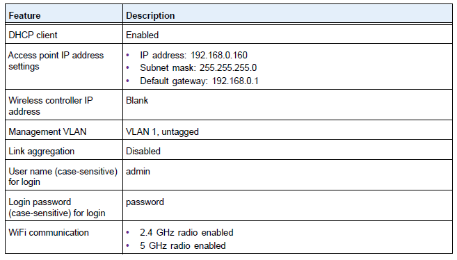
Table 3. Technical specifications
Pros & Cons
Pros
- High-speed data transfer with 802.11ac support
- Robust security features, including WPA2 and 802.1X authentication
- Centralized management through the ProSafe Network Management System
- Support for PoE and Gigabit Ethernet ports
- Durable design suitable for wall or ceiling mounting
Cons
- Higher cost compared to consumer-grade access points
- A complex setup may require IT expertise
- No built-in controller; requires an external management system
- Limited compatibility with older network devices
Customer Reviews
Customers have praised the Netgear ProSafe AC Access Point WAC740 for its reliable performance and strong signal coverage. Many reviewers appreciate the ease of central management through Netgear’s ProSafe Network Management System. However, some users have noted that the initial setup can be complex and may require technical expertise. Common complaints include the higher cost compared to consumer-grade options and occasional firmware issues that require updates.
Faqs
What is the maximum speed supported by the Netgear ProSafe AC Access Point WAC740?
Does the Netgear ProSafe AC Access Point WAC740 support Power over Ethernet (PoE)?
How many simultaneous client connections can the Netgear ProSafe AC Access Point WAC740 handle?
What advanced security features does the Netgear ProSafe AC Access Point WAC740 offer?
Can I manage multiple Netgear ProSafe AC Access Points centrally?
What is the recommended mounting method for the Netgear ProSafe AC Access Point WAC740?
How do I troubleshoot poor signal strength issues with the Netgear ProSafe AC Access Point WAC740?
Is the Netgear ProSafe AC Access Point WAC740 compatible with older network devices?
What are some common complaints about the Netgear ProSafe AC Access Point WAC740?
Does the Netgear ProSafe AC Access Point WAC740 come with a built-in controller?
More netgear manuals
- Setup & Features: Netgear Wireless Router User Manual
- Netgear AC750 WiFi Range Extender EX2800 User Manual
- Setup & Features: Netgear AC1200 WiFi Range Extender EX6110 User Manual
- Netgear Nighthawk AX8 WiFi Mesh 6 Extender EAX80 User Manual
- Setup & Features: Netgear AC750 WiFi Range Extender EX3110 User Manual
- Netgear 802.11ac Wireless Access Point WAC104 User Manual
Leave a Comment