Progressive Dynamics Power Control Converter PD4000 User Guide

Content
Introduction
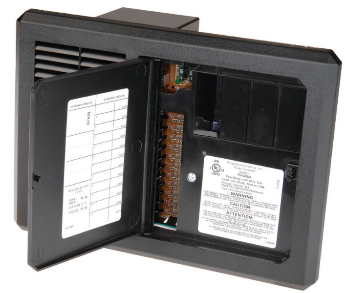
The Progressive Dynamics Power Control Converter PD4000 is a compact and efficient power distribution system designed for recreational vehicles and other applications requiring reliable electrical management. This all-in-one unit combines a 45 or 60 Amp converter with an AC distribution panel, allowing for easy integration and control of multiple circuits. Featuring advanced safety features like reverse battery protection and thermal overload protection, it ensures optimal performance. Priced at approximately $234.00, it is an essential component for enhancing power management in RVs.
The PD4000 Series POWER CONTROL CENTER offers break-through technologies that help maintain and lengthen the life of your batteries such as our patented Charge Wizard.
The heart of the PD4000 is the INTELI-POWER Converter. The built-in Charge Wizard microprocessor constantly monitors the battery voltage then automatically adjusts the converter output voltage to provide the proper charging voltage for fast recharges and long-term maintenance.
The intelligent way to charge and maintain your RV battery. With enough AC and DC branches you’ll have plenty of options for your growing RV needs.

Specifications
Specifications (Specificationssubject to changewithout notice) | ||
Model | PD4045 | PD4060 |
AC Section | 120 VAC 30 Amps Maximum - 7 BranchCircuits Max * | |
DC Section | 12 VDC60A Max. - 12 BranchCircuits | 12 VDC75A Max - 12 Branch Circuits |
| Input: 105-130VAC 50/60 Hz | Input: 105-130VAC 50/60 Hz |
Converter Section | 725 Watts Output: 13.6 VDC, 45 Amps | 1000 Watts Output: 13.6 VDC, 60 Amps |
| Weight: 5.70 lbs | Weight: 6.35 lbs |
* Consult local regulatory authority for possible branch circuit restrictions
Description
With its sturdy build and cutting-edge electronics, the Progressive Dynamics Power Control Converter PD4000 is designed to dependable performance even in the most challenging settings. The converter's small size makes it ideal for installations in confined areas. In order to prevent typical problems like overvoltage, overcurrent, and excessive heat, it has numerous protection systems.
In addition, the PD4000 has an automated temperature compensation function that maintains peak performance by adjusting the output voltage according to the surrounding temperature. Recreational vehicles and maritime vessels alike can benefit from this converter's constant and dependable DC output.
Installation Instructions
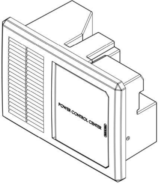
- The PD4000 series POWER CONTROL CENTER should be installed horizontally (converter section to the left).
- Unit is NOT ignition protected. Do not mount in the LP gas or the battery compartment.
- Cut mounting hole to approximately 10 3/4” wide X 7 1/4” high.
- Connect wiring system using proper connections and appropriately sized cable clamp. A closure plug kit for any unused Romex connectors may be purchased from Progressive Dynamics, Inc. Part Number PD812374.
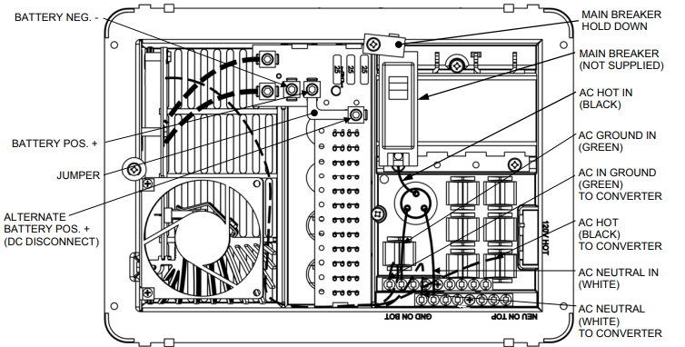
- For installations without an external DC disconnect switch connect battery POS (+) to the BATTERY POS. + lug. The ALTER-NATE BATTERY POS. + lug is not used. (see wiring diagram for lug locations)
DC DISCONNECT
For installations incorporating an external DC disconnect switch, connect battery POS (+) and the BATTERY POS. + lug to the same pole on the external disconnect switch.
Remove the JUMPER. Connect the ALTERNATE BATTERY POS. + to other pole on the external disconnect switch. (see wiring diagram for component locations)
The OEM should test the POWER CONTROL CENTER converter under full load conditions in its intended mounting location to ensure proper ventilation. Failure to provide adequate ventilation will prevent the converter from supplying full output power.
The INTELI-POWER converters are not designed for zero clearance compartments.
The POWER CONTROL CENTER is not designed for wet or damp locations. Install in an interior / dry location.

Detailed Wiring Diagram
Note: Some factory installed wiring not shown for clarity.

Note: Above image may vary, depending on model.
Consult a licensed electrician or an RV technician for installation assistance
Setup Guide
To operate the Progressive Dynamics Power Control Converter PD4000, follow these steps:
- To avoid overheating, make sure the converter is placed in an area with enough ventilation.
- Make that the voltage falls within the stated range before connecting the AC input to a power source.
- In accordance with the established protocols, link the DC output to the load or the battery bank.
- Before using a multimeter or other diagnostic equipment to ensure appropriate operation, turn on the power source.
- Make any other required configuration changes, such as enabling certain safety features or adjusting the output voltage.
User Information
Many options will be installed prior to the purchase of your new RV, however there are a few options that you should be aware of while operating your new POWER CONTROL CENTER.
The PD4000 series incorporates a microprocessor to provide a three-stage charge profile to ensure rapid, yet safe recharging of 12 volt batteries. These three separate stages
BOOST, NORMAL, and STORAGE modes ensure that the battery is automatically recharged and maintained with minimum maintenance (i.e. reduced need to add water).
- BOOST MODE: If the converter senses that the battery voltage has dropped below a preset level the output voltage is increased to approximately 14.4 volts DC to rapidly recharge the battery.
- NORMAL MODE: Output voltage set at approximately 13.6 volts DC.
- STORAGE MODE: When the converter senses that there has been no significant battery usage for 30 hours the output voltage is reduced to 13.2 volts DC for minimal water usage. When in storage mode the microprocessor automatically increases the output volt-age to 14.4 volts DC for 15 minutes every 21 hours to help reduce sulfation of the battery plates.
All times and voltages provided above are approximate. -
CAUTION
IT IS IMPORTANT THAT THE FLUID LEVEL OF ANY CONNECTED BATTERIES BE CHECKED ON A REGULAR BASIS. ALL BATTERIES WILL “GAS” AND LOSE SOME FLUID WHEN CONTINUOUSLY CONNECTED TO ANY CHARGING SOURCE.
~Does not apply to “gel-cell” batteries~

REVERSE BATTERY PROTECTION CIRCUIT
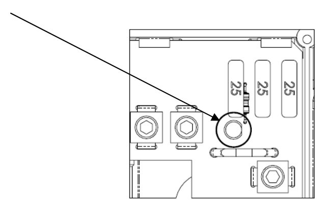
If a battery is accidentally hooked up backwards, the converter will be protected. Easily accessible ATC type fuses will blow when a battery is connected in reverse. Correct battery wiring and replace fuses with same type and rating. The LED will glow if one of the fuses blow. Appropriate fuse size is indicated on the circuit board.

DC Section
The DC panel features up to 12 fused positions rated for up to 30 amps for accessories.
CAUTION
FOR CONTINUED PROTECTION AGAINST RISK OF FIRE OR ELECTRICAL SHOCK, REPLACE ONLY WITH SAME TYPE AND RATING FUSE.
AC RATING
- COPPER WIRE ONLY. RATED 75 C MIN
- MAXIMUM SERVICE: 30 AMPS, 120V 50/60 HZ SINGLE PHASE
- LINE TERMINALS SIZE 6-14 AWG
- LOAD TERMINALS SIZE 6-14 AWG
- NEUTRAL AND GROUND SIZE 6 - 14 AWG
- SHORT CIRCUIT CURRENT RATING:
- SUITABLE FOR USE ON NO MORE THAN
- 120 VOLTS AC, 10,000 AMPERES MAX,
- LIMITED TO THE LOWEST INTERRUPTING
- CAPACITY OF ANY BREAKER INSTALLED
MAXIMUM CONTINUOUS LOADS ON MAINS OR BRANCH CIRCUITS NOT TO EXCEED 80% OF THE CIRCUIT BREAKER RATINGS
NEUTRAL/GND WIRE COMBINATIONS:
- (1) #12 STRANDED & (1) #14 SOLID
- (1) #12 STRANDED & (1) #14 STRANDED
- (1) #12 SOLID & (1) #14 STRANDED
- (1) #12 SOLID & (1) #14 SOLID
- (2) #14 STRANDED OR (2) #14 SOLID
- (2) #12 STRANDED OR (2) #12 SOLID
- (2) #10 STRANDED OR (2) #10 SOLID
TORQUE DATA
LINE TERMINAL: SEE CIRCUIT BREAKER
NEUTRAL BAR & GROUND:
- #4 - #6 35 IN. LBS
- #8 30 IN. LBS
- #10 - #14 25 IN. LBS
Progressive Dynamics Power Control Converter PD4000 Troubleshooting
PROBLEM | POSSIBLE CAUSES | ACTION |
No Output |
120 VAC supplynot connected | Connect powersupply |
| Check AC distribution panelfor proper operation | ||
Reverse batteryfuses blown (See page 2 for location) | Check for reverse batteryconnection. | |
| Replace fuseswith same typeand rating (Seepage 2) | ||
| Short circuit | Trace RV circuits for possible fault | |
| Unit has shutdown due to overheating | Check air flow | |
| Allow unit to cool | ||
Unit has shutdown due to over voltage (Converter will shutdown if theinput voltage exceeds 132 VAC) | Check inputvoltage | |
| Correct inputvoltage | ||
Low Output | Compartment gets too hot | Check air flow to the converter |
| Improve ventilation to the compartment | ||
| Excessive loadfor converter | Reduce loadrequirements or installlarger converter | |
| Input voltagenot between 105-130 VAC | Correct inputsupply voltage | |
| Bad battery cell(s) | Replace battery | |
Intermittent or no Outputon Generator, works on Shore Power | Unit has shutdown due to over voltage. | Add anotherload to the generator, thismay reduce the “spikes” to an acceptable level |
Some generators exhibit excessive voltage spikes on the AC poweroutput, this maycause the overvoltage protection to shut the unit down | Contact generator manufacturer for possible defect in the generator |
Consult a licensed electrician or an RV technician for installation assistance
Do not replace the converter section unless the following checks have been performed:
- Use an AC voltmeter to check for the proper voltage at the 120 VAC breaker that the converter is connected to. This voltage should be between 105 and 130 volts.
- Remove the reverse battery fuses and check the converter output from the CONVERTER GND to the CONVERTER POS terminals on the DC board. This should be 13.6 VDC.
- Check the Reverse Battery fuses . These fuses will only blow if the battery or DC output leads were connected in reverse, even for a moment. If they are blown check the polarity of the battery connections before replacing them.
- If the Converter output is not present and there is AC to the converter , the converter is defective.

Make sure all power is disconnected before proceeding.
- Remove the neutral, ground, and hot wires that lead to the converter on the AC side.
- Remove the converter output wires from the DC board, ground and positive.
- Finally unscrew the screw that holds the metal converter plate to the plastic housing.
For factory repairs, return only the converter section.
Make sure you use proper packaging to ensure the product’s safe arrival.
Pros & Cons
Pros
- Design that maximizes efficiency while minimizing power loss
- Exceptionally dependable operation thanks to sturdy build and cutting-edge electronics
- A constant voltage output is ensured by automatic temperature correction.
- Improved durability with integrated cooling system
- Various safeguards to prevent damage from excessive heat, overcurrent, and voltage
Cons
- A bit more expensive than competing converters
- In order to achieve peak performance, it must be installed and configured correctly.
- For enclosed areas, it may be necessary to install supplemental ventilation systems to avoid overheating.
Customer Reviews
Consistent performance and dependability have earned the Progressive Dynamics Power Control Converter PD4000 high marks from satisfied customers. Users have praised its reliability and the fact that it can withstand heavy loads without failing or overheating. The installation process, according to some users, can be intricate and detail-oriented.
Common complaints
Think about the greater price tag in comparison to alternatives and the requirement for adequate ventilation to keep operating temperatures optimal.
WARRANTY
DURATION
This warranty shall extend for a period of two years from the original date of purchase, and is valid only within the continental limits of the United States and Canada.
Faqs
What is the input voltage range for the Progressive Dynamics?
How much output current can the PD4000 handle?
Does the Progressive have built-in protection features?
What is automatic temperature compensation in the Power Control Converter?
Can I use the Progressive Dynamics Power Control Converter in marine applications?
Why does my Progressive Converter keep tripping its protection mechanisms?
How important is ventilation for the Control Converter PD4000?
What are some common complaints about the Progressive Dynamics?
Is the Converter PD4000 easy to install?
Leave a Comment
