
Quatro JS-5293 JetStream Dust Collector User Manual
Content
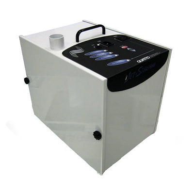
Overview
The JS-5293 JetStream Dust Collector is a compact, two-stage dust and fume collection system designed to capture debris at the source and improve indoor air quality in bench-top and CAD/CAM work environments. It combines strong suction, quiet operation, and intelligent controls in a space-saving format that fits well in dental labs, milling stations, and other precision work areas.
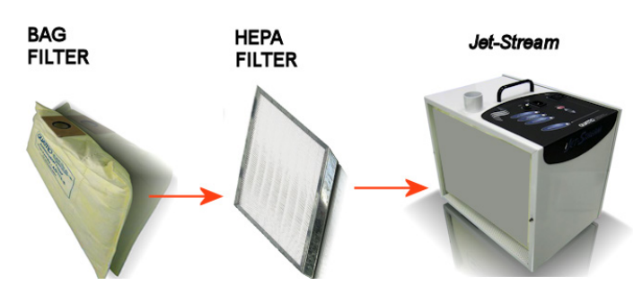
At its core, the JS-5293 JetStream Dust Collector uses a bag filter for larger particles and a HEPA filter for finer contaminants, making it a practical choice for users who need reliable particulate capture without a bulky footprint.
Specifications
- Model: JS-5293
- Nominal airflow: 110 CFM
- Approximate size: 13 in high x 11 in wide x 15 in deep
- Voltage options: 115V / 1 phase / 60 Hz or 230V / 1 phase / 50 Hz
- Current and power: 7 amps, 825 watts at 115V; 4 amps, 750 watts at 230V
- Approximate weight: 28 lb
- Inlet size: 1.5 in diameter
- Filtration stages: Bag filter plus HEPA filter
Detailed Description
The JS-5293 JetStream Dust Collector is built around a compact enclosure with quick access to both the filter compartment and motor compartment. Its filtration path is designed to trap larger debris first, then remove fine airborne particles through the HEPA stage. The system also includes i Series controls with LED status indicators, speed adjustment buttons, and remote-operation capability for compatible equipment.
Key internal and external elements include the power inlet, circuit breaker, DB9 remote connector, filter access panel, motor access panel, and the on-unit control buttons. The control system monitors motor condition, filter loading, standby state, and shutdown alarms so users can respond before performance drops or damage occurs.
Safety
- This dust collector must be used with the correct voltage, a grounded outlet, and only the supplied power cord. It should not be operated with missing filters, restricted airflow, kinked hoses, or in damp locations.
- Keep the unit at least 6 inches away from walls and nearby objects, especially around the discharge area, so it can ventilate properly and avoid overheating. Always turn the system off before unplugging it, opening the covers, changing filters, or servicing the motors. The motors may remain hot after shutdown, so allow a cooling period before touching internal parts.
- The system is intended to stay plugged in and should be switched on and off with its own power control rather than by cutting power at the wall or using a switched outlet. It is not meant for explosive, highly flammable, or toxic materials, and all local safety regulations should be followed during installation and use.
Setup and operation
Before startup, place the unit in its final location, open the filter access panel, and install the filters in the correct order.
Connect the hose or arm to the inlet, then plug the power cord directly into the wall outlet. The dust collector does not need warm-up time and can be started only when needed.
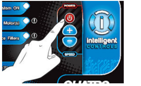
The red power button controls manual operation, while the up and down buttons adjust airflow. If the extraction level is adequate, the unit can be run at maximum speed for best removal performance. AUTOFLOW is designed to maintain effective suction by increasing motor speed as filter resistance rises, then returning toward the original speed after filter replacement.
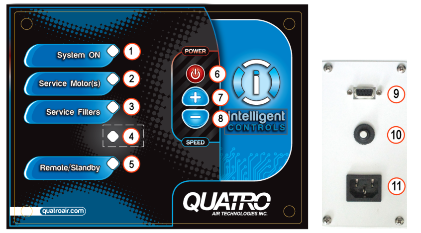
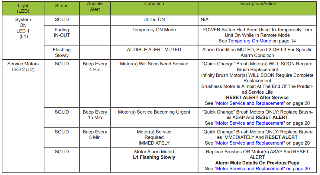
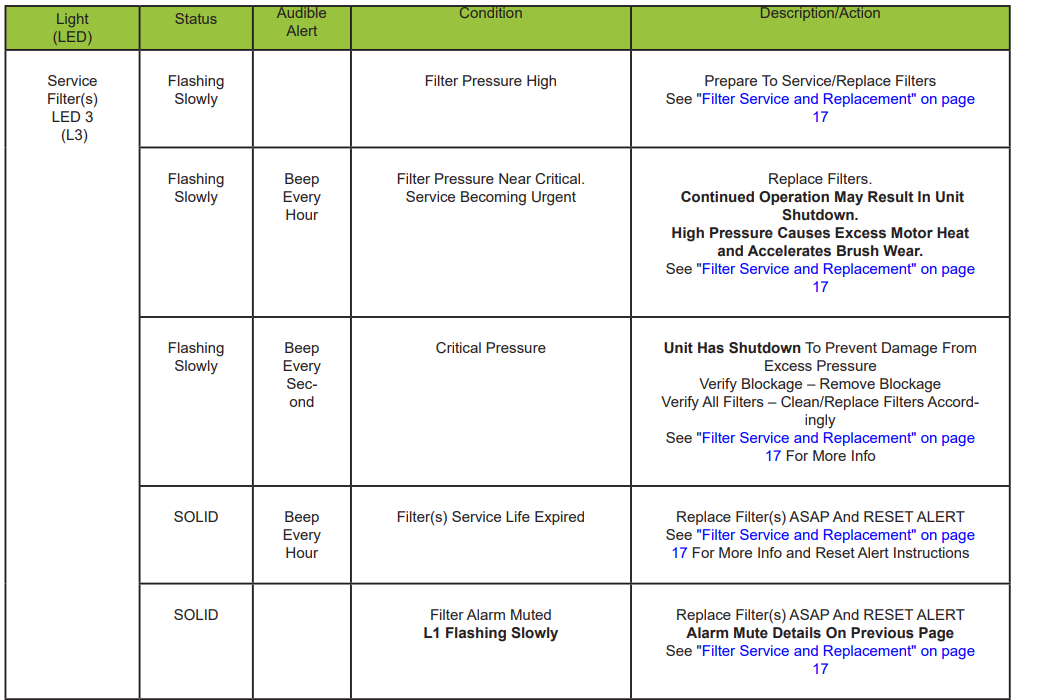
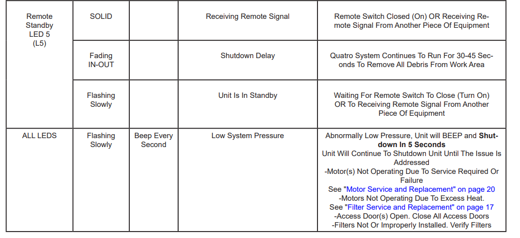
The i Series LEDs communicate operating status and service needs. The system-on light confirms power state, the service motor light warns when brush wear or motor life is nearing its limit, the service filter light shows when filter pressure is rising or service is due, and the remote/standby light shows remote activity or waiting state. A temporary mute function can silence alarms for 8 hours.
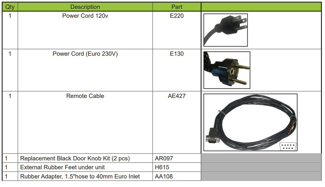
Remote operation is supported through the DB9 connector and the AE427 remote cable. The unit can respond to a closed dry contact or a 1-30V AC/DC signal, and it also provides run and fault status outputs for compatible external equipment. When remote control is active, the on-panel power button is limited until the remote/standby state allows manual override.
For remote use, the unit starts when it receives a signal and stops after a built-in delay of about 30 seconds when the signal ends. That shutdown delay cannot be disabled, so control software should be set to use the shortest possible stop interval.
Light Diagnostics Table
DB9 Pin Out Information
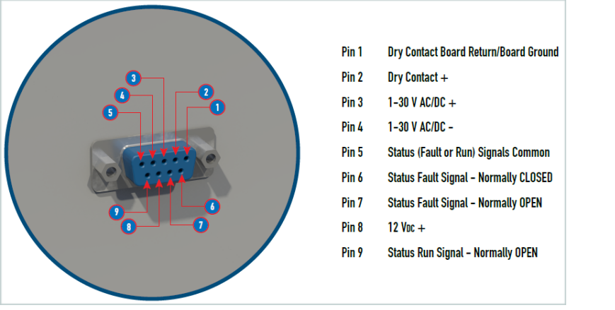
Jet-Streams support remote operation. Connect the AE427 remote cable in between the Quatro System and the other piece of equipment using only the wires required as per the diagram below.
Remote Status
The System can output status signals to your equipment.
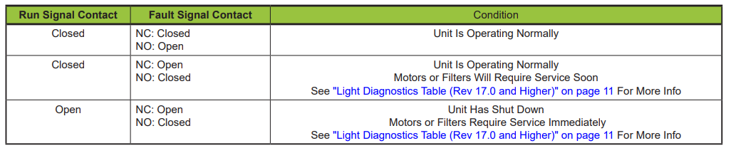
- The Run Signal contact is CLOSED whenever the system is turned on (motor(s) are functioning). The contact is OPEN when the unit is turned off (motor(s) are not functioning). This includes when the unit goes into Remote/Standby and if the unit shuts down due to a problem. Run signal will NOT open when the motor(s) shut off for a filter cleaning when operating in “Online” filter cleaning mode. Critical Filter Pressure Alarms (high and low pressure) will OPEN the Run Signal and shut the motor(s) off.
- The Fault Signal can be used either with a Normally Open (NO) or Normally Closed (NC) contact depending on which wire you choose to use (see diagram on previous page). When there ARE NO alarm conditions present the NO contact will remain open and the NC contact will remain closed. When there ARE alarm conditions the NO contact will CLOSE and the NC contact will OPEN. ALL LEVELS of Filter and Motor(s) service alarms will trip the Fault Signal. The Quatro Run Signal can only shut down the piece of equipment controlling it remotely if the piece of equipment supports that function. The piece of equipment must be set or programmed to shut itself off when the Quatro Run signal is OPENED. Contact your equipment manufacturer to verify if your equipment supports that function. The status signals can either return a “signal” provided by your equipment or output a 12VDC+ or 12VDC-, depending on how the AE427 remote cable is wired. The Quatro System uses a single “common” for both the Run and Fault Signals.
- To return a “signal” connect your signal to the Brown wire (Pin 5).
- The “returned” Run signal is available on the Violet wire (Pin 9).
- The “returned” Fault NC (Normally Closed) is available on the Blue wire (Pin 6).
- The “returned” Fault NO (Normally Open) is available on the Orange wire (Pin 7).
- To be supplied with a 12vdc signal where the + is being switched, connect the Yellow Wire (Pin 8) to the Brown wire (Pin 5).
- The 12VDC+ Run signal is available across the Violet wire (Pin 9+) and the Black Wire (Pin 1-).
- The 12VDC+ Fault NC (Normally Closed) is available across the Blue wire (Pin 6+) and the Black Wire (Pin 1-).
- The 12VDC+ Fault NO (Normally Open) is available across the Orange wire (Pin 7+) and the Black Wire (Pin 1-).
- Any combination of the Dry Contact, Run Signal and Fault Signal being used means the Black Wire (Pin 1) must be shared. c. To be supplied with a 12vdc signal where the - is being switched, connect the Black Wire (Pin 1) to the Brown wire (Pin 5).
- The 12VDC- Run signal is available across the Violet wire (Pin 9-) and the Yellow Wire (Pin 8+).
- The 12VDC+ Fault NC (Normally Closed) is available across the Blue wire (Pin 6-) and the Yellow Wire (Pin 8+).
- The 12VDC+ Fault NO (Normally Open) is available across the Orange wire (Pin 7-) and the Yellow Wire (Pin 8+).
- Any combination of the Dry Contact, Run Signal and Fault Signal being used means the Black Wire (Pin 1) must be shared.
Your “signal” will be managed as indicated on the table below. The combination of the Run and Fault Signals can tell you if the unit is still running but has an alarm condition or if there is an alarm condition and the unit has shut down completely.
Filter Service and Replacement
Proper maintenance is critical to extend the life of the filtration system. The information presented below outlines basic maintenance procedures ensuring the unit will provide trouble-free operation for years to come. The Jet-Stream is designed to allow quick access to the filters.
LED Diagnostic Table - “Service Filter(s)” Alerts (iSeries Controls)
- If “Service Filter(s)” alert is FLASHING SLOWLY most likely the bag filter need to be replaced.
- If “Service Filter(s)” alert is ON SOLID replace the HEPA filter.
Replacement Instructions
Access to all filters is through the filter-side cover for the Jet-Stream System.
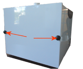
Unfasten the 2 thumb wheel nuts that secure the filter access panel to the chassis and remove the panel. The filter bag is now visible.
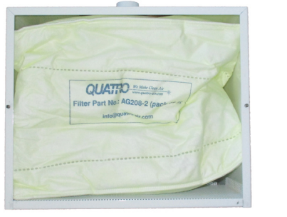
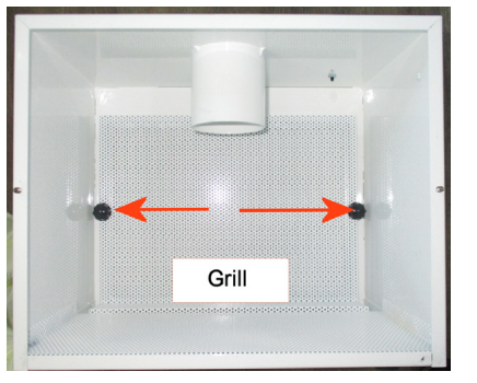
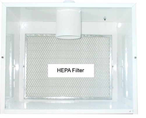
Slide the filter bag downward off the inlet collar and remove. The HEPA filter is housed behind a protective grill secured with 2 thumb wheel nuts.
Remove the two nuts and lift out the grill. The HEPA filter is now visible.
Replace your filters using the appropriate parts.
Resetting Service Filters Alert
If the Service Filters LED does not extinguish on its own after changing the filters, follow this reset procedure.
- Ensure filter access door is closed.
Plug power back to the unit.
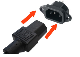
- When you Press “POWER”, MOTOR WILL START.
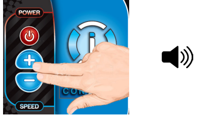
While motor is operating, press and hold SPD-UP and SPD-DN simultaneously until unit beeps. Hold for 10+ seconds; when panel is beeping continuously, release buttons. In this condition, “System ON” LED is FLASHING quickly.
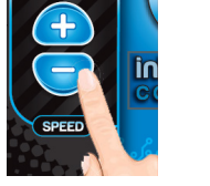
Press SPD DN until “Service Filters” LED is FLASHING.
Press and HOLD POWER button while Service Filter(s) LED is FLASHING and unit is BEEPING continuously. Release button when unit stops BEEPING.
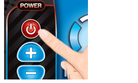
- LED will be OFF and unit will be ready to operate again.
Replacement Filter Part Numbers
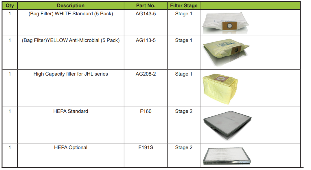
General Filter Maintenance Guide

Replacement Parts
Cleaning and maintenance
The filter system is not washable or reusable, so maintenance is based on replacement rather than cleaning. The bag filter is typically the first stage to service, while the HEPA filter is replaced when the filter alert stays solid.
To change filters, remove the filter-side cover by loosening the thumb nuts, slide the bag filter off the inlet collar, and lift out the HEPA filter after removing its protective grill. Dispose of used filters according to local rules.
Reset the service filter alert after replacement if it does not clear automatically. The reset sequence uses the control panel buttons and requires the access door to be closed before the motor is started and the service menu is entered.
Motor service depends on the installed motor type. Quick-change brush motors allow brush replacement in the field, while Infinity motors are replaced at end of life. To reach the motor assembly, remove the side access panel on the opposite side from the filters. After motor service or replacement, the service motor alert must be reset, and new brushes should be broken in at low speed for about 20 minutes.
Troubleshooting
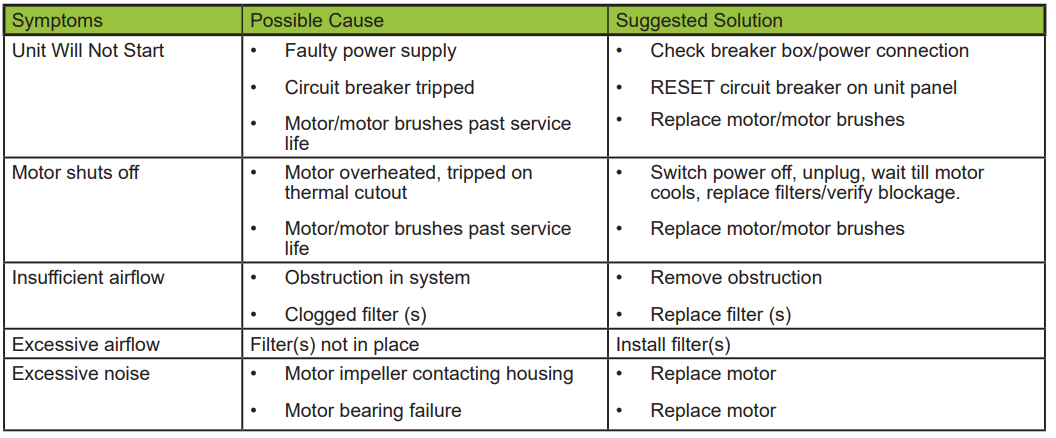
If the unit will not start, check the power source, the circuit breaker, and whether the motor or motor brushes have reached the end of service life. If the unit shuts off during use, the most common causes are overheating or worn motor components.
Low airflow usually points to a blockage in the system or clogged filters. Excess airflow typically means the filters are missing or not installed correctly. Unusual noise can indicate an impeller contacting the housing or a failing motor bearing, both of which require motor replacement.
Warranty
Quatro Air Technologies provides a one-year warranty from the shipment date against defects in materials and workmanship under normal use and service. The warranty is limited to replacement of defective parts.
The coverage excludes abuse, misuse, neglect, improper assembly, vandalism, modifications, non-recommended parts, and operation at the wrong voltage. Wear items and damage caused by improper power removal are also excluded, and only original Quatro-approved parts should be used for repair.
Pros & Cons
- Pros: Compact footprint, two-stage filtration, HEPA protection, quiet operation, variable speed control, and remote-operation support.
- Pros: Clear LED diagnostics make it easier to track filter and motor service needs.
- Pros: Quick access panels simplify routine maintenance.
- Cons: Filters are disposable rather than cleanable.
- Cons: Motor service is required over time, and some models use consumable Infinity motors.
- Cons: The unit must be set up carefully with the correct voltage, airflow clearance, and filter installation to avoid shutdowns.
Faqs
How do I set up the JS-5293 JetStream Dust Collector before first use?
What is the correct startup process for the JS-5293 dust collector?
What do the iSeries control lights and alarms on the JS-5293 mean?
How does AUTOFLOW work on the JS-5293 JetStream Dust Collector?
How do I replace the bag filter and HEPA filter on the JS-5293?
Why is the JS-5293 showing a Service Filters alert after I replaced the filters?
How do I use remote operation on the JS-5293 JetStream Dust Collector safely?
What should I do if the JS-5293 will not start or has very low airflow?
More quatro manuals
- Quatro iVAC Premium Series Turbine Dust Collector User Manual
- Setup: Quatro Fresh-Air Purifier AF400DM User Manual
- Installation: Quatro DFH-1000 Ductless Fume Hood User Manual
- Setup: Quatro Rh-Series Desktop Containment System Owner Manual
- Quatro Jet-Stream Tall Premium Dust Collectors User Manual
- Setup: Quatro CollectALL MedEVAC MultiPure PowerStation PS2 Owner Manual
Leave a Comment