Wen 9-Inch Band Saw Fence & Miter 3959 Guide
Content
Introduction of WEN 9-Inch Band Saw Fence & Miter 3959
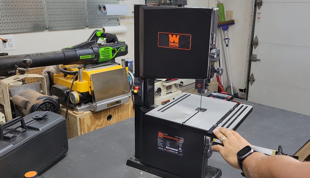
The WEN 9-Inch Band Saw Fence & Miter is a versatile and durable accessory designed to enhance the functionality and accuracy of your band saw. This fence and miter guide is compatible with most 9-inch band saws, making it a valuable addition to any woodworking shop. With an estimated price of $30-$40, this guide is a cost-effective solution for improving your band saw's performance and precision. The WEN 9-inch Band Saw Fence & Miter 3959 Guide is now available for purchase, providing woodworkers with an essential tool for their woodworking projects.
Description
The WEN 9-Inch Band Saw Fence & Miter 3959 Guide is crafted from heavy-duty aluminum and features an easy-to-read scale, ensuring accurate and consistent cuts. The guide's robust construction provides stability and minimizes vibration, leading to smoother cuts and improved overall performance. The fence attachment is simple to install, allowing for rapid adjustments to accommodate various materials and cut depths. The miter guide features a large, easy-to-grip handle for easy positioning and adjustments, and it can be locked into place, providing consistent and accurate miter cuts. The WEN 9-Inch Band Saw Fence & Miter 3959 Guide is an indispensable tool for woodworkers looking to maximize their band saw's potential.
UNPACKING
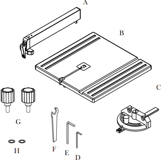
- Guide Fence
- Work Table Assembly (with Hex Bolt, Lock Washer, Flat Washer and Wing Nut)
- Miter Gauge
- S2 Hex Wrench
- S4 Hex Wrench
- 10 mm Wrench Table Lock Knobs (2) D6 Flat Washers (2)
KNOW YOUR BAND SAW


EXPLODED VIEW AND PARTS LIST

EXPLODED VIEW AND PARTS LIST
No. | Part No. | Description | Qty. | No. | Part No. | Description | Qty. | ||
| 1 | 3959-001 | Lower Door | 1 | 35 | 3959-035 | Upper Guide Slide Bar | 1 | ||
| 2 | 3959-002 | Hex Screw M6X10 | 2 | 36 | 3959-036 | Hex Screw M4X4 | 1 | ||
| 3 | 3959-003 | Spring WasherΦ6 | 3 | 37 | 3959-037 | Pin 5X14 | 4 | ||
| 4 | 3959-004 | Nut M6 | 5 | 38 | 3959-038 | Upper Blade Guide Support | 1 | ||
| 5 | 3959-005 | Screw M4X10 | 4 | ||||||
39 | 3959-039 | Upper SupportShaft | 1 | ||||||
| 6 | 3959-006 | Window | 1 | ||||||
40 | 3959-040 | Flat Washer M5 | 3 | ||||||
| 7 | 3959-007 | Upper Door | 1 | ||||||
41 | 3959-041 | Ball Bearing | 2 | ||||||
| 8 | 3959-008 | Saw Blade | 1 | ||||||
42 | 3959-042 | Bearing Fastening Screw | 2 | ||||||
| 9 | 3959-009 | Shaft Circlip | 2 | ||||||
43 | 3959-043 | Hex Screw M5X10 | 3 | ||||||
10 | 3959-010 | Bearing | 4 | ||||||
44 | 3959-044 | Hex Screw M5X12 | 4 | ||||||
11 | 3959-011 | Hole Circlip Φ26 | 4 | ||||||
45 |
3959-045 | Philips Screw+Flat Washer+Spring WasherAssembly M4X8 |
6 | ||||||
12 | 3959-012 | Screw M4X8 | 2 | ||||||
13 | 3959-013 | Rubber Gasket | 2 | ||||||
14 | 3959-014 | Driven Pulley | 1 | ||||||
46 | 3959-046 | Belt | 1 | ||||||
15 | 3959-015 | M8X70 Bolt | 1 | ||||||
47 | 3959-047 | Hex Nut M12X1.5 | 1 | ||||||
16 | 3959-016 | Brush | 1 | ||||||
48 | 3959-048 | Spring WasherM12 | 1 | ||||||
17 | 3959-017 | Scale Label | 1 | ||||||
49 | 3959-049 | Lower Wheel Shaft | 1 | ||||||
18 | 3959-018 | Upper Wheel Shaft | 1 | ||||||
50 | 3959-050 | Hex Screw M5X10 | 1 | ||||||
19 | 3959-019 | Upper Wheel ShaftBase | 1 | ||||||
51 | 3959-051 | Big Flat Washer | 1 | ||||||
20 | 3959-020 | Split Washer M6 | 2 | ||||||
52 | 3959-052 | Driven Pulley | 1 | ||||||
21 | 3959-021 | Connection Shaft | 1 | ||||||
53 | 3959-053 | Guide Plate | 1 | ||||||
22 | 3959-022 | Blade Wheel | 2 | ||||||
54 | 3959-054 | Hex Nut M10 | 1 | ||||||
23 | 3959-023 | U Type Support | 1 | ||||||
55 | 3959-055 | Hex Screw M6X8 | 2 | ||||||
24 | 3959-024 | Bolt | 1 | ||||||
56 | 3959-056 | Blade Lower Guard | 1 | ||||||
25 | 3959-025 | Hex Nut M4 | 2 | ||||||
57 | 3959-057 | Saw Body | 1 | ||||||
26 | 3959-026 | Switch | 1 | ||||||
58 | 3959-058 | Block | 1 | ||||||
27 | 3959-027 | Switch Plate | 1 | ||||||
59 | 3959-059 | Tension Spring | 1 | ||||||
28 | 3959-028 | Locking Washer | 1 | ||||||
60 | 3959-060 | Tension Handle | 1 | ||||||
29 | 3959-029 | Guide Base | 1 | ||||||
61 | 3959-061 | Flat Washer D8 | 2 | ||||||
30 | 3959-030 | Screw | 7 | ||||||
62 | 3959-062 | Hex Nut M8 | 1 | ||||||
31 | 3959-031 | Guide Cover | 1 | ||||||
63 | 3959-063 | Wing Locking Nut | 1 | ||||||
32 | 3959-032 | Cover Spring | 1 | ||||||
64 | 3959-064 | Blade Wheel Adjusting Knob | 1 | ||||||
33 | 3959-033 | Screw | 1 | ||||||
65 | 3959-065 | 6P4 Clip | 2 | ||||||
34 | 3959-034 | Slide Board | 1 | ||||||
No. | Part No. | Description | Qty. | No. | Part No. | Description | Qty. | ||
66 | 3959-066 | Power Cord | 1 | 98 | 3959-098 | Miter Gauge Pointer | 1 | ||
67 | 3959-067 | Hex Screw M8X25 | 2 | 99 | 3959-099 | Lower SupportShaft | 1 | ||
68 | 3959-068 | Flat Washer M8 | 1 | 100 | 3959-100 | Lower Blade Guide Support | 1 | ||
69 | 3959-069 | Motor | 1 | ||||||
101 | 3959-101 | Spring WasherD10 | 1 | ||||||
70 | 3959-070 | Locking Knob | 1 | ||||||
102 | 3959-102 | Capacitor | 1 | ||||||
71 | 3959-071 | Eccentric LockingKnob | 2 | ||||||
103 | 3959-103 | Philips Screw+Flat Washer M4X6 | 2 | ||||||
72 | 3959-072 | Flat Washer D6 | 2 | ||||||
73 | 3959-073 | Hex Screw M6X25 | 2 | ||||||
104 | 3959-104 | Capacitor Box | 1 | ||||||
74 | 3959-074 | Adjusting Gear | 1 | ||||||
105 | 3959-105 | Wavy Washer Φ6 | 1 | ||||||
75 | 3959-075 | Adjusting HandleBase | 1 | ||||||
106 | 3959-106 | Lower Blade Guide Sup- port Base | 1 | ||||||
76 | 3959-076 | Adjusting Handle | 1 | ||||||
77 | 3959-077 | Dust Port | 1 | 107 | 3959-107 | Hex Bolt M6X40 | 1 | ||
78 | 3959-078 | Hex Bolt M6X20 | 4 | 108 | 3959-108 | Wrench S=10 | 1 | ||
79 | 3959-079 | Hex Nut M6 | 5 | 109 | 3959-109 | Hex Wrench S=4 | 1 | ||
80 | 3959-080 | Shaft | 1 | 110 | 3959-110 | Hex Wrench S=2 | 1 | ||
81 | 3959-081 | Locking Spring | 2 | 111 | 3959-111 | Screw M4X8 | 4 | ||
82 | 3959-082 | Gear Handle | 1 | 112 | 3959-112 | Spring WasherD8 | 1 | ||
83 | 3959-083 | Table Pointer | 1 | 113 | 3959-113 | Screw M5X16 | 3 | ||
84 | 3959-084 | Hex Bolt M6X25 | 1 | 114 | 3959-114 | Flat Washer D6 | 3 | ||
85 | 3959-085 | Table Insert | 1 | 115 | 3959-115 | Fence LockingPlate | 1 | ||
86 | 3959-086 | Work Table | 1 | 116 | 3959-116 | Fence LockingSpring | 1 | ||
87 | 3959-087 | Table Locking Knob | 2 | 117 | 3959-117 | Fence Washer | 2 | ||
88 | 3959-088 | Fence LockingKnob | 1 | 118 | 3959-118 | Hex Bolt M6X16 | 2 | ||
89 | 3959-089 | Angle Support | 1 | 119 | 3959-119 | Fence Plate | 1 | ||
90 | 3959-090 | Hex Bolt M6X12 | 4 | 120 | 3959-120 | Fence Work Rest | 1 | ||
91 | 3959-091 | Pin 3X16 | 1 | 121 | 3959-121 | Bolt | 1 | ||
92 | 3959-092 | Butterfly Nut M6 | 1 | ||||||
93 | 3959-093 | Flat Washer D6 | 4 | ||||||
94 | 3959-094 | Slide Bar | 1 | ||||||
95 | 3959-095 | Miter Gauge Knob | 1 | ||||||
96 | 3959-096 | Miter Gauge | 1 | ||||||
97 |
3959-097 | Philips Screw+Flat Washer+Spring WasherAs- sembly M5X8 |
1 | ||||||
Setup of Band Saw Fence & Miter
Setting up the WEN 9-Inch Band Saw Fence & Miter Guide is a straightforward process
- Begin by attaching the fence to the band saw's table using the included mounting screws.
- Adjust the fence's position using the easy-to-read scale, ensuring it is parallel to the band saw blade.
- Install the miter guide by sliding it onto the band saw's blade and locking it into place using the thumbscrew.
- Adjust the miter guide's angle as needed by loosening the locking knob and rotating the guide to the desired degree. Once set, tighten the locking knob to secure the angle.
ASSEMBLY & ADJUSTMENT
WARNING: Unplug the machine from the power source before assembly and making adjustments. Failure to comply may cause serious injury. Assembly requires at least two people to safely move around the band saw.
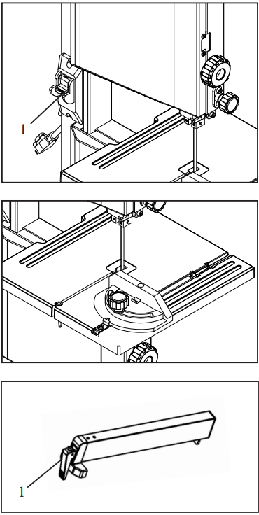
ASSEMBLING THE TABLE
- Remove the M6X24 hex bolt, spring washer, flat washer and wing nut from the work table assembly
- Slide the saw table onto the band saw, making sure that the blade stays within the slot in the table
- Pull the angle adjustment knob on the back of the band saw and align the teeth on the table bracket into the teeth on the angle adjustment knob. Release the knob.
- Assemble the flat washers and table lock knobs into the table bracket. Turn the table lock knobs to tighten the table assembly to the saw’s frame.
- Reattach the hex bolt, spring washer, flat washer and wing nut onto the front of the table

TILTING THE TABLE
- Loosen the two table lock knobs located on the back of the band saw
- Adjust the table to the desired angle using the angle adjustment knob and the angle indicator. The table can be tilted 45 degrees to the right.
- Use the angle indicator to confirm the desired angle and tighten the table lock knobs (NOTE: a table perpendicular to the blade corresponds to a scale indication of 0°).
MOUNTING THE BAND SAW
The band saw should be firmly attached to a reliable work surface. This will prevent the band saw from vibrating, walking or tipping during operation. Mount your band saw using bolts, flat washers, lock washers and hex nuts (not included) through the mounting holes on the base of the saw
CONNECTING TO THE DUST COLLECTION
Connect your band saw to the dust collection system of your choice (not included) using the dust port on the back of the unit The outer diameter of the port is 2-1/2 inches. Hose adaptors (not included) may be needed depending on the size of your dust hose.
NOTE: Always operate in a well-ventilated area and use dust collection systems whenever possible.
WARNING: Always be sure that the tool is switched off and unplugged before making any adjustments. Wear work gloves when handling saw blades. Failure to comply may cause serious injury.

SAW BLADE TRACKING
Before initial cutting and after every blade change, check and adjust blade tracking so that the blade runs on the center of the wheels.
- Turn off the band saw and unplug it from the power supply. Make sure that the blade is not moving, then open both the upper and lower wheel covers
- Stand to the side of the saw in the position shown in Fig. G. Carefully rotate the upper wheel manually for at least three rotations (making sure not to touch the blade) and watch the blade travel. If the blade is veering off to either side of the wheel, follow the next step to adjust blade tracking.
- Loosen the blade tracking lock. Continue to rotate the wheel and slowly turn the blade tracking knob in the desired direction until the blade is centered over the wheels. Turning the blade tracking knob towards you shifts the blade to the left, and turning it away from you shifts the blade to the right.
- Spin the wheel a few more turns to ensure that the blade is now running consistently in the center of the wheel. Close and lock the covers.
NOTE: Blade tracking will be more difficult with thinner blades, but don’t be frustrated. Keep at it and you’ll get there!

ADJUSTING THE BLADE TENSION
Proper tensioning of the blade is important before operating the band saw. If the tension in the blade is too high, it runs the risk of breaking. If the tension is too low, there is a risk of the blade slip-ping and stopping during a cut.
- Loosen the blade guard lock knob located on the back of the saw. Raise the blade guard to the top by turning the blade guard adjustment knob. Lock the blade guard.
- Check the tension by tapping with a finger against the side of the blade halfway between the table and the upper guide. The blade should not flex more than 2 mm.
WARNING: Wear protective gloves when handling saw blades. - Turn the tension knob clockwise to increase the blade tension or counterclockwise to decrease tension. Check and adjust the tension as necessary to make sure the blade is properly tensioned.

UPPER BLADE GUIDES ADJUSTMENT
The upper blade guides need to be readjusted after every blade change or blade tracking adjustment.
- Upper Thrust Bearing
Loosen the upper right screw using the S4 hex wrench to adjust the position of the thrust bearing running along the back of the blade. The bearing should be positioned 0.5 mm from the back of the blade. Retighten the screw - Upper Side Guides
Loosen the two set screws using the S2 hex wrench to adjust the two side guides at either side of the blade. The side guides should be positioned 0.25 mm away from the blade (Fig. J). Retighten the set screws
Loosen the lower right screw using the S4 hex wrench. Move the screw to position the side guides 1 to 2 mm from the teeth of the blade. Retighten the screw
LOWER BLADE GUIDES ADJUSTMENT
The lower blade guide needs to be readjusted after every blade change or blade tracking adjustment.
- Open the lower wheel cover. The table might need to be removed for easier access to the adjustment screws.
- The procedure is the same as adjusting the upper guides. Loos-en the lower screw to adjust the thrust bearing 0.5 mm from the back of the blade. Loosen the upper screw to adjust the side guides 1 - 2 mm from the teeth of the blade. Loosen the two set screws to adjust the side guides 0.25 mm away from the either side of the blade.
- Close the lower wheel cover.

BLADE GUARD ADJUSTMENT
The height of the upper blade guard should be adjusted prior to every operation to accommodate the height of the workpiece. NOTE: The blade guard should be no more than 1/8 of an inch from the upper edge of the workpiece.
- Loosen the blade guard locking knob located on the back of the saw
- Turn the blade guard adjustment knob to adjust the height of the blade guard. Lock the upper blade guide locking knob to secure the guard in place once the desired height has been reached.

CHANGING THE BAND SAW BLADE
WARNING: Saw blades can be dangerous. Wear work gloves while handling the blade or when moving new blades from the packaging.
- Remove the M6X24 hex bolt, spring washer, flat washer and wing nut from the work table assembly.
- Open the upper and lower blade covers
- Set the upper blade guard to its lowest position, minimizing the space between the bottom of the blade guard and the table assembly.
- Open the blade guard cover by pushing down on the top of the cover, and simultaneously pulling it outwards, away from the wheel.
- Loosen the tension knob until you can remove the blade from the machine.
NOTE: Now is a good time to clean out your band saw to ensure the best performance. Clear out any sawdust, wood chips, etc. with a shop vacuum. Ensure that the wheels and tires are free of sawdust and chips. This promotes good wheel balance and good blade tracking. - Fit the new blade through the guiding slots on both the left and right sides of the machine onto the upper and lower rubber tires. Position the blade in the center of the rubber tires. Ensure that the blade teeth are pointing down towards the table.
- Turn the blade tensioning knob clockwise to put the new blade under tension
- Close the upper blade guide assembly cover by pushing in until it clicks in place.
- Replace the M6X24 hex bolt, spring washer, flat washer and wing nut onto the work table assembly.
- After every blade change, make sure to follow the instructions on page 10 and 11 to adjust the tracking of the blade, the blade tension, and the upper and lower blade guides. Proper tuning of your band saw is necessary to ensure the optimum performance of the machine.
- After all adjustments and tuning are complete, close the upper and lower wheel covers.

OPERATION
SUGGESTIONS AND WARNINGS
- Do not touch the saw blade when cutting.
- During saw operation, wear safety glasses but do not wear gloves.
- Cut only one workpiece at a time.
- Always hold the workpiece down on the table.
- Do not jam any workpieces.
- Do not try to slow the blade down by pushing the workpiece against the saw blade from the side.
- When straight cutting against the fence, use a push stick.
- Use a work support when cutting long stock to avoid pieces from falling down after the cut has been completed.
- Use a dust collector to minimize sawdust.
- When cutting round stock, make sure the piece is as secure as possible.
- Before starting, check that the saw blade and the upper and lower blade guides are in proper working order.
- Replace damaged parts immediately.
- Assume the correct working position (the blade’s teeth should be pointing
- Take all necessary precautions to avoid kickback during operation.
ON/OFF SWITCH
- To turn the saw ON, move the switch to the up position. To turn the saw OFF, move the switch to the down (OFF) position.
- To lock the switch in the OFF position
- Wait until the band saw has come to a complete stop.
- Remove the safety key from the switch housing. Store the safety key in a safe place.
- To unlock the switch and turn the saw ON, insert the safety key into the switch, and move the switch to the ON position.
USING THE MITER GAUGE
- Place the miter gauge into the slot on the table
- Loosen the knob on the gauge to set a new miter angle (between 0 and 60 degrees).
- Tighten the knob firmly before cutting begins.
NOTE: A 0° cut is a straight cut that is perpendicular to the blade.
USING THE FENCE
The fence acts as a guide for making straight cuts. Position the fence onto the work table with the side face is parallel to the blade. Adjust the distance of the fence to the blade depending on the length you would like to cut. Lock it in place by pushing down on the fence lock handle . Make sure the fence is locked down before operation.
ELECTRICAL INFORMATION
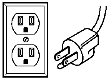
GROUNDING INSTRUCTIONS
- IN THE EVENT OF A MALFUNCTION OR BREAKDOWN, grounding provides the path of least resistance for an electric current and reduces the risk of electric shock. This tool is equipped with an electric cord that has an equipment grounding conductor and a grounding plug. The plug MUST be plugged into a matching outlet that is properly installed and grounded in accordance with ALL local codes and ordinances.
- DO NOT MODIFY THE PLUG PROVIDED. If it will not fit the outlet, have the proper outlet installed by a licensed electrician.
- IMPROPER CONNECTION of the equipment grounding conductor can result in electric shock. The conductor with the green insulation (with or without yellow stripes) is the equipment grounding conductor. If repair or replacement of the electric cord or plug is necessary, DO NOT connect the equipment grounding conductor to a live terminal.
- CHECK with a licensed electrician or service personnel if you do not completely understand the grounding instructions or whether the tool is properly grounded.
- USE ONLY THREE-WIRE EXTENSION CORDS that have three-pronged plugs and outlets that accept the tool’s plug Repair or replace a damaged or worn cord immediately.
- CAUTION: In all cases, make certain the outlet in question is properly grounded. If you are not sure, have a licensed electrician check the outlet.
WARNING: This tool is for indoor use only. Do not be exposed to rain or use in damp locations.
GUIDELINES AND RECOMMENDATIONS FOR EXTENSION CORDS
Make sure your extension cord is in good condition. When using an extension cord, be sure to use one heavy enough to carry the current your product will draw. An undersized cord will cause a drop in line voltage resulting in loss of power and overheating. The table below shows the correct size to be used according to cord length and nameplate ampere rating. When in doubt, use a heavier cord. The smaller the gauge number, the heavier the cord. Make sure your extension cord is properly wired and in good condition. Always replace a damaged extension cord or have it repaired by a qualified person before using it. Protect your extension cords from sharp objects, excessive heat and damp/wet areas. Use a separate electrical circuit for your tools. This circuit must not be less than a #12 wire and should be protected with a 15 A time-delayed fuse. Before connecting the motor to the power line, make sure the switch is in the OFF position and the electric current is rated the same as the current stamped on the motor nameplate. Running at a lower voltage will damage the motor.
WARNING: This tool must be grounded while in use to protect the operator from electric shock.
SPECIFIC RULES FOR BAND SAWS
- To avoid injury from unexpected movement, make sure the saw is on a firm, level surface. Bolt the saw to a support surface to prevent slipping or sliding during operation. Make sure there is adequate space for operations. The mounting holes are 7 mm in diameter, 118 mm apart in width and 353 mm apart in length.
- Use the correct size and style of blade. Inspect blades for cracks and missing teeth before each use. Do not operate with dull, cracked or badly worn blades. Dull blades require more effort to use and are difficult to control.
- When replacing blades, make sure the blade teeth are pointing down and towards the table. Check that the blade is properly tensioned before operating.
- Blade guides, blade tracking and tensioning must be properly adjusted to optimize performance and minimize blade breakage.
- To maximize blade support, always adjust the upper blade guide and blade guard so that it barely clears the workpiece. The blade guard should be no more than 1/8 of an inch from the upper edge of the workpiece
- Do not operate this band saw without the blade guards in place.
- Make sure the table adjustment knob is locked and the table is secure before operation.
- Workpieces should be secured so they don’t twist, rock, or slip while being cut. Small pieces should be secured with clamps or fixtures. Do not hold small pieces with your hand because your fingers might go under the blade guard.
- Use extra caution with very large, very small, or awkwardly shaped workpieces.
- Plan intricate or small work carefully to avoid pinching the blade. Avoid awkward operations and hand positions to prevent accidental contact with the blade.
- Support roundwork properly (use a V block or press it against the miter gauge) to prevent it from rolling.
- Use a work support when cutting long stock to avoid pieces from falling down after the cut has been completed.
- Cut only one workpiece at a time. Make sure the table is clear of everything except the workpiece and its guides before you turn the saw on.
- Never position fingers or thumbs in line with the cut. Serious personal injury could occur.
- Always watch the saw run before each use. If there is excessive vibration or unusual noise, stop immediately. Turn the saw off and unplug it immediately. Do not start the saw again until the problem has been located and corrected.
- Do not attempt to stop or slow the blade with your hand or a workpiece. Wait for the blade to stop on its own.
- To free any jammed material, turn the switch off. Remove the switch key and unplug the saw. Wait for all moving parts to stop before removing the jammed material.
- Take all necessary precautions to avoid kickback during operation.
- Plan your cuts so you always cut entirely through the wood. Do not back the workpiece away from the blade while the saw is running. If you need to remove the blade from a partially cut workpiece, you first must turn the band saw OFF and wait for the blade to come to a complete stop. Do not twist or put excessive stress on the blade while removing it from a workpiece.
- Don’t leave the work area until all moving parts have stopped. Shut off the power to master switches. Remove the switch key from the band saw and store it in a safe place, away from children. Childproof the workshop!
- Switch the power to OFF and remove the plug before performing any inspections, adjustments, and maintenance. Wait for all moving parts to come to a complete stop.
- If any part of this band saw is missing, broken, bent, or damaged in any way, or if any electrical component fails to perform properly, shut off the power switch, remove the machine plug from the power source, and have the damaged, missing, or failed parts replaced before operation.
WARRANTY
WEN Products is committed to build tools that are dependable for years. Our warranties are consistent with this commitment and our dedication to quality. LIMITED WARRANTY OF WEN CONSUMER POWER TOOLS PRODUCTS FOR HOME USE GREAT LAKES TECHNOLOGIES, LLC (“Seller”) warrants to the original purchaser only, that all WEN consumer power tools will be free from defects in material or workmanship for a period of two (2) years from date of purchase. Ninety days for all WEN products, if the tool is used for professional use.
Troubleshooting of Band Saw Fence & Miter 3959
Some common issues that may arise when using the WEN 9-Inch Band Saw Fence & Miter include
- Inaccurate cuts: If you notice inaccuracies or inconsistencies in your cuts, double-check that the fence and miter guide are properly aligned and securely fastened to the band saw.
- Excessive vibration: Ensure that the fence and miter guide are installed correctly and that all screws and locking mechanisms are tightened securely. If vibration persists, check for any signs of wear or damage on the band saw's table or blade.
- Difficulty adjusting the miter guide: If you find it challenging to adjust the miter guide's angle, verify that the locking knob is properly loosened before attempting to rotate the guide. If the issue persists, ensure that the thumbscrew is not obstructed and that it can slide smoothly along the band saw blade.
Pros & Cons of WEN 3959
Pros
- Improves accuracy and consistency
- Heavy-duty aluminum construction
- Easy-to-read scale and adjustment knobs
- Compatible with most 9-inch band saws
- Affordable solution for enhanced performance
Cons
- May not fit all 9-inch band saw models
- The miter guide locking mechanism might be challenging to adjust for beginners
Customer Reviews of WEN 9-Inch Band Saw Fence & Miter 3959
Customers have praised the WEN 9-inch Band Saw Fence & Miter for its durability, ease of use, and ability to significantly improve the precision of their band saw cuts. The guide's affordability and compatibility with various band saw models have made it a popular choice among woodworkers. However, some users have reported difficulties in installing the guide on specific band saw models, so ensuring compatibility before purchasing is essential.
Faqs
The WEN 3959 9-Inch Band Saw is capable of cutting through what kinds of materials?
With my WEN 3959 Band Saw, what is the correct way to set it up?
How many different safety features does the WEN 3959 Band Saw come equipped with?
Can you tell me how to adjust the tension on the blades of the WEN 3959?
What steps should I take if the blade of my band saw moves about while I am cutting?
Which of the following is the maximum capacity of the WEN 3959 Band Saw for cutting?
What is the best way to troubleshoot the WEN 3959 when it is stalled or has limited cutting power?
What is the best way to troubleshoot the WEN 3959 when it is stalled or has limited cutting power?
How should I go about lubricating the WEN 3959? What kind of oil should I use?
Regarding the WEN 3959, is there a warranty included?
Leave a Comment