Xblue X16 Office Phone System User Guide | Usage & Functions
Content
Introduction
The X16 system is a full-featured, next-generation, multi-line business telephone system ideal for both home and small office environments. It comes equipped to interface with 4 Central Office (CO) Lines, equipped to receive Caller ID, and sixteen (16) proprietary digital telephone endpoints. The system can be expanded to accommodate an additional two (2) CO Lines, allowing a maximum configuration of six central office telephone lines. Or the system may be configured with 4 CO Lines and 2 Voice over IP (VoIP) Session Initiation Protocol (SIP) Media Gateways and sixteen proprietary digital telephone endpoints. In addition, the system comes standard with Auto Attendant and all digital telephone endpoints have a personal digitally integrated voice mailbox.
Detailed Specifications
The xblue Networks X16 Office Phone System boasts the following key features:
- 16 programmable keys
- 5-inch color display
- Built-in Bluetooth and Wi-Fi
- 100-hour backup battery
- Integrated with CRM and other business applications
- Support for up to 16 extensions
- PoE (Power over Ethernet) support
- Gigabit Ethernet ports
- HD audio
- Advanced security features, including SRTP and TLS
Features
- Auto Attendant
- Intercom Paging
- Answering Machine Emulation
- Meet me Answer (Paging)
- Audible and Visual Ringing
- Memo Recording
- Backlit LCD Display
- Message Waiting (Telco-FSK)
- Call Timer
- Multilingual Display per Extension
- Call Transfer
- Music on Hold Internal/External
- Caller ID and Call Waiting Caller ID
- Mute with LED indication
- CO Line Busy/Idle Status (LED)
- Navigation Keys
- CO Line Ringing (programmable)
- New/All Message Play
- Conference (3-way)
- Voice Mail
- Conversation Recording
- Phone Book Dialing
- Daylight Savings (Automatic with Caller ID)
- Programmable Buttons (12)
- Direct Mailbox Transfer
- Programmable Pause (Speed Bins)
- Direct Station Select – Busy Lamp Field
- Redial
- Display Number Dial
- Remote Message Pickup
- Distinctive Ringing
- Ringer Volume Control
- Do Not Disturb
- Set Time and Date
- Flash Timer
- Speakerphone with LED
- Handset/Headset Volume Control
- Speed Dial Buttons
- Headset Activation
- Time in Display
- Hold
- Tone/Pulse
- Intercom Calling
- Voice over IP (VoIP) - future
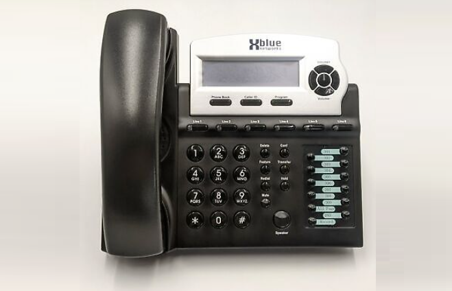
Telephone Callouts
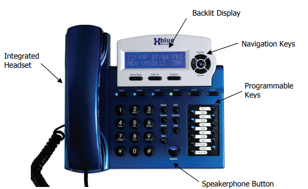
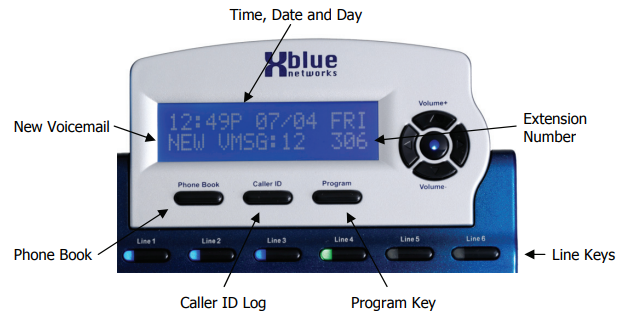
Backlit LCD Display
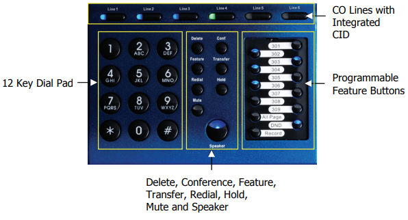
Button Layout
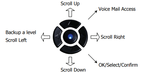
X16 Office Phone System Navigation keys
Scroll left or right, up and down to update the LCD Display.
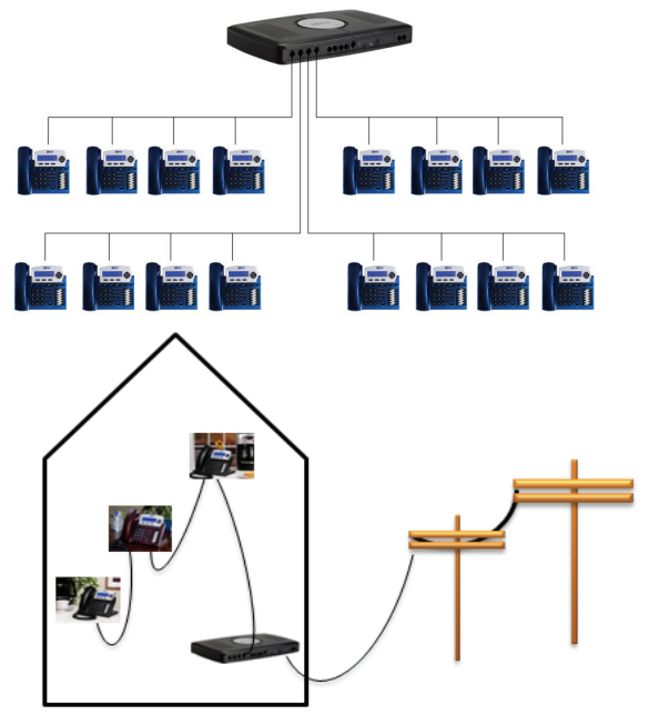
System Configuration
The system uses advanced digital interface technology. One cable pair supports up to four digital telephone endpoints. Each digital telephone endpoint has its own extension number and can be called from any other extension in the system.
Xblue Networks X16 Office Phone System Description
Businesses can benefit from a robust and flexible communication solution with the xblue Networks X16 Office Phone System. The X16 makes it easy to access important features and operations with its 5-inch color display and 16 configurable keys. The 100-hour backup battery guarantees ongoing communication during power outages, and the built-in Bluetooth and Wi-Fi features make it easy to integrate with mobile devices. Businesses of all sizes will find the X16's advanced security features and support for up to sixteen extensions to be an ideal fit.
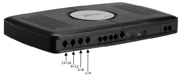
Installation
The X16 comes standard with four RJ11 extension ports. Each port supports up to 4 proprietary digital telephone endpoints, for a total of sixteen (16) endpoints. Each port on the system will support up to 600 feet of cable. In a star topology, 600 feet is calculated by adding each Digital Telephone endpoint's cable run. Cable A + Cable B + Cable C + Cable D <= 600 feet. In a serial cable topology, 600 feet is calculated by adding the distance of the initial run plus the distance between each telephone. Cable A to telephone 1 + (distance between telephone 1 & telephone 2) + (distance between telephone 2 & telephone 3) + (distance between telephone 3 & telephone 4) <= 600 feet.
Location
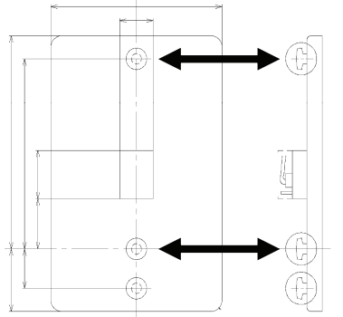
The system should be located close to the telephone company interface (RJ21X), and have a dedicated outlet with an isolated ground. The system can be mounted on the wall or placed on a table. Once the location of the system is determined, use the supplied wall mounting template to level and secure the system with the provided screws, or place it on a table.
Line up the back of the system with the four screws, and slide it into place.
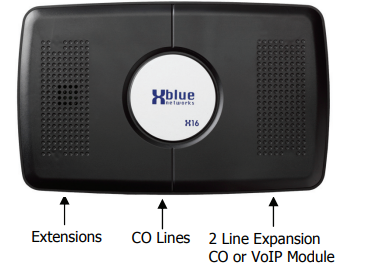
CO Line Connections
Using the matrix below, connect the CO Lines to the system using one RJ14 connector per CO Line. The port labeled Line 1 is a direct access auxiliary port for line 1 allowing an analog device direct access.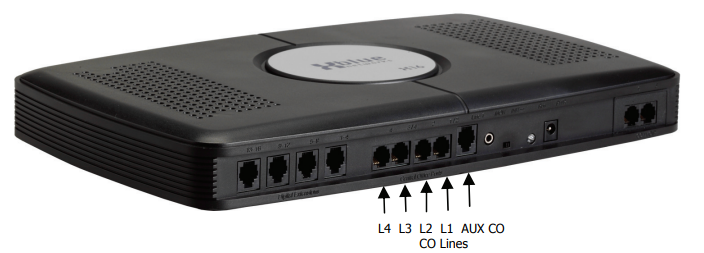
Line Port Number Connection AUX CO Line1 CO Line 1 1 / 2 CO Line 2 CO Line 2 2 CO Line 3 CO Line 3 / 4 CO Line 4 CO Line 4 CO Line 5 CO Line 5 CO Line 6 CO Line 6 Telephone Endpoint Connection
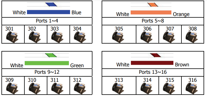
Connect telephone endpoints to the system using one RJ11 port for up to 4 different endpoints, with a maximum of 600 feet per port. Once connected, each telephone endpoint will register with the voice server when it is powered up. At default, the extensions begin with number 301. The remaining extension numbers must be entered.
Correct Installation Process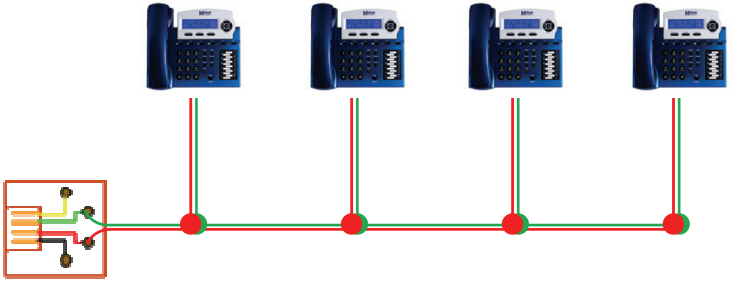
It is important to connect a telephone to every jack that is connected to the system. Extensions connected to a cable with “Bridge Taps” may experience distortion. If locating a bridge tap is not practical, a quick resolution is to use a different cable pair such as the Yellow/Black or White/Orange.
Incorrect Installation Process DO NOT leave any ports open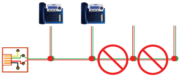
X16 Cable Pair
Leaving any ports punched down but not connected to a telephone may result in erratic operation. When mounting a Digital Telephone Endpoint, be sure to use the inner posts on an adjustable wall mount plate.
Punch Down
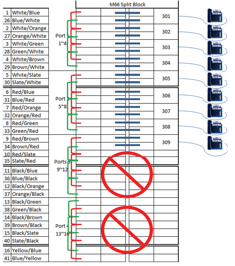
In this example, system ports 10 through 16 do not have telephones connected to them but they are still “punched down” on the system. There is a potential that extensions, especially extension 309 in this example, may experience distortion.
Power up and Initialization
Connect the power to power on the system. To initialize the system, once the blue LED begins flashing at 1 impulse per second (IPS), switch the “init switch” back and forth three times and the LED will begin flashing at a rapid rate for 5 seconds and then return to 1 IPS. For proper operation, be sure to reset, by unplugging, the system after all extensions are connected.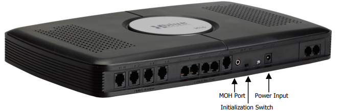
- Extension Numbering of X16 Office Phone System
One extension will automatically be numbered 301; all other extension numbers will have to be entered at the time of installation. Valid numbers are 302 to 399. The system becomes fully functional after all extensions are registered. Extensions may be moved from one port to another simply by unplugging the unit and plugging it into another active port. If the extension is unplugged for longer than 120 seconds (2 minutes), the port may initialize and revert back to factory default – This includes all personal voice mail settings. Any port that is active must have either a telephone or an Endpoint Device connected to it, or distortion may be heard.
Note: An “Endpoint Device” may be needed when relocating an extension.
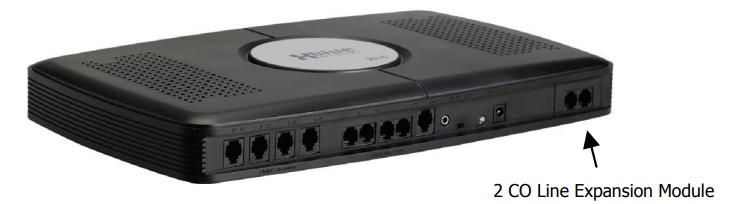
Expansion Module
The X16 system comes with four CO Lines and is expandable to six CO Lines. The two-line expansion module can be either a CO Line module or a two-channel VoIP Gateway Module. The expansion module mounts inside the communication server and connects to the main board via ribbon cable. When the system is powered on, the expansion module will be recognized in software and fully operational. Use the following steps to install the expansion module.
- Installing the Expansion Module
Place the voice server face down on a stable surface such as a table, showing the four rubber feet.

Remove the four rubber feet, placing them in a safe place, such as the back of the voice server, exposing 4 screws. Unscrew the four screws and remove the cover.

Insert the Expansion Module
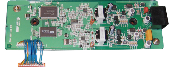
- Remove the plastic tab found on the front of the Voice server. Insert the RJ14 (RJ48 for VoIP) connections through the front of the voice server and secure the card with the provided screws. Connect the ribbon cable from the expansion module to the main board and replace the cover. Place the provided black plastic encasement window around the newly installed card.
Endpoint Device
Every live telephone jack connected to the system will receive a data signal. If the system finds an open jack (bridge tap), the data signal may be lost, causing the remaining digital telephone endpoints to receive erroneous data, which may lead to improper operation. Therefore, for proper operation, each live telephone jack connected to the system must have either a digital telephone endpoint or an endpoint device.
Symptoms of an open jack include – but are not limited to – voice distortion, static, slow speakerphone reaction when the button is pressed, problems accessing CO Lines, etc.

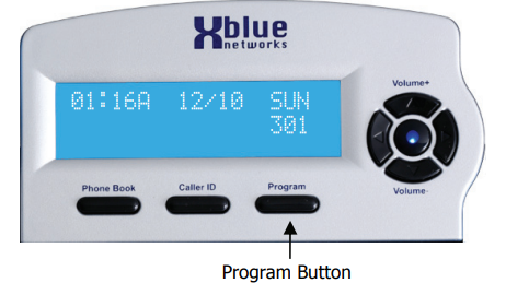
X16 Office Phone System Programming
The system has two areas of programming; Phone (extension) and System. The system programming parameters affect the whole system, whereas the Phone programming parameters will only affect the extension that is doing the programming.
From an Idle telephone press the program button.
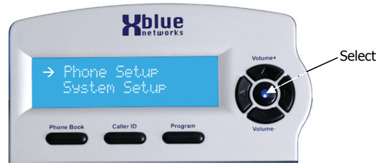
The navigation keys are used to select the area of programming to be modified, Phone or System Setup.
Extension parameters such as voicemail will remain for up to 120 seconds when an extension is unplugged or being relocated. To relocate an extension simply unplug it and plug it into another extension port.
Note: Extension will appear busy to all other extensions when they are in Programming or reviewing caller ID.
Navigation Keys
Navigating through programming

Phone Setup Parameters
| Feature | Default (shown in bold) |
|---|---|
| Language | English, French, Spanish |
| Feature Key | |
| Extension No. | 301 – 399 |
| Auto Mute | Off |
| Preference Call | Intercom or CO Call |
| Line Selection | 1 – 4 |
| Record All Call | Off |
| Hold Reminder | 30 |
| Ringer On/Off | On (CO Line 1 – 6) |
| Ringer Type | 1 (CO Line 1 – 6) |
| Call Forward | VoiceMail/External/TRK to TRK/Off |
| Voice Mail Setup | |
| Remote code | 123 |
| Personal OGM | |
| Clear My MSG | |
| Call Screening | On |
| User Name | |
| Reset Phone |
Note: Extension will appear busy to all other extensions when they are in Programming or reviewing caller ID.
Phone Setup
- Phone Setup
The parameters are used by the end user to customize their telephones. - Language
Each telephone user can select between three different languages; English, Spanish, and French. - Feature Key
Each extension has 12 programmable buttons which can be customized by each user. - Extension Number
Valid numbers are 301 through 399. Changing this number may result in a loss of extension configuration settings. Changing this parameter will result in the loss of some extension settings, such as voicemail notification. - Auto Mute
This feature is used to allow extensions to call you, and make an announcement; your microphone is automatically muted so callers cannot hear the conversation. This is also called Page Mode. - Preference Call
The user can select from accessing a CO Line or Intercom when going off hook. - Line Selection
Each digital telephone endpoint user can set their telephone to directly access a CO Line or group of lines. Record all Calls
This parameter, when enabled, will record all network calls answered by this extension.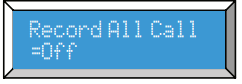
When a call is placed on hold this timer starts. Each time this timer expires, a beep is heard to remind the extension user that a call is on hold.

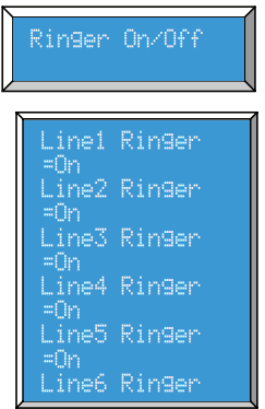
Extension users can program CO Lines to ring (on), or not ring (off), by pressing the up or down navigation key. Each CO Line can be programmed individually.
Ringer Type
Each extension user can select from 6 different ring tones for each of the 6 CO Lines. Press the navigation key up or down to scroll through the different tones.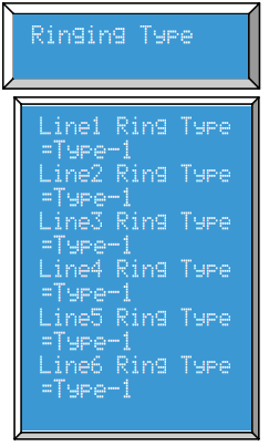
- Call Forward
Each extension can select where calls will be forwarded to when they are busy or when a call goes unanswered.- Waiting Time
The call waiting time is the amount of time a call will ring before it is sent to the programmed destination. Waiting Time uses the up or down navigation key to select from 10 to 25 seconds. Forward Destination
Extension users may select from three destinations; Off, Voice Mail, External Call, and Trunk2Trunk.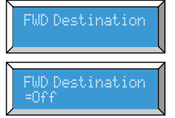
- Off: Calls will not forward
- Voice Mail: Calls will be forwarded to the users’ personal mailbox. The center navigation button will be lit solid.
- External: The system will transfer an incoming caller, using a second CO Line, to an external destination.
Note: External Call forward uses two CO Lines, and you may experience a volume loss when analog lines are connected using this feature. Also, toll charges may apply. If all CO Lines are busy, the call will not forward. - TRK2TRK
Allows calls to be transferred to an external destination using the telephone networks facilities. This may require special features from the network provider.
- Waiting Time
Phone Number
Enter the telephone number to be dialed when the External or TRK2TRK forward timer expires. This can be any external telephone number such as a cellular or home telephone number.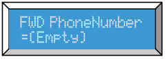
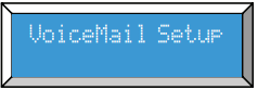
Each extension can set up their own voice mail parameters.
- Remote Code
The remote code is the code that an extension user will dial to access voice mail from a remote location. Personal OGM
This greeting is heard by a caller once they are forwarded to someone’s voice mailbox. Press the Select button to Play and Stop the existing message, press the up button to re-record the Outgoing Message.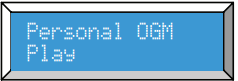
User Name
Each extension can be programmed to display up to 12 characters of the extension user’s name. Once in the name entry field, the dial pad becomes the character input keyboard. Each depression of the number will change the character in the following way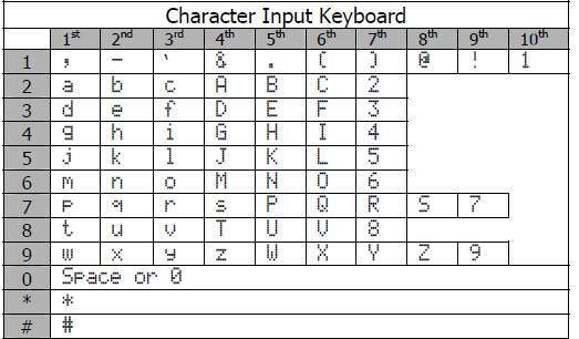
- Reset Phone
The reset function will bring the digital endpoint back to default. Press the up navigation key to select “Yes?” to default and “No?” to not default the telephone.
Programming Feature Buttons
Each digital telephone endpoint has twelve (12) programmable feature buttons, which can be customized by each extension user. There are three programmable feature button categories.
- Press the program button
- Select phone setup
- Press the select (center) navigation key
- Press the down navigation key and select “Feature Key”
- Press the center navigation button to begin
Press the up or down navigation key to select the feature button to be programmed or press the feature key to be programmed.
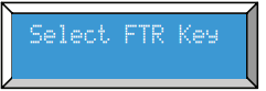
The display will show the selected FTR button. The display below shows FTR#01, FTR button 1, was pressed
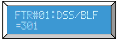
Press the Program button to exit programming and not modify the current button programming or press the center button to change the current setting.
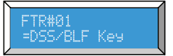
- Using the up or down navigation key, select between DSS/BLF, Speed Key, or Feature.
- Press the select button to display the current programmed function.
- Enter the appropriate extension, speed dial number or use the up or down navigation keys and select the desired feature.
- Press the select button to confirm the selection.
Voice Mail Operation
The System comes equipped with a 4-channel auto attendant and voice mail system, which can answer up to 4 different calls simultaneously.
Auto Attendant
The system can be programmed to answer in “Auto Attendant” mode. When Auto Attendant is set to “On-AA Ring Only” the attendant telephone will ring until the “Waiting Time” expires. When Auto Attendant is set to “Off-AllEXT Ring” all telephones programmed to ring will ring until the “Waiting Timer” expires. Once the Auto Attendant answers, the caller may dial the desired extension number.
Personal Mailbox
Each extension is automatically assigned a personal mailbox, which is used to play a personal greeting and record a message. In addition, all extensions are automatically forwarded to their mailbox. Once forwarded to voice mail the center navigation key will be lit solid, indicating that the telephone has been forwarded to voice mail. Be sure to record the OGM so that callers will receive your personal message. Once forwarded, all calls that are transferred to that extension will be forwarded to the user’s personal mailbox and will hear their OGM (Outgoing Message).
Memo Recording
Each extension can press their record button to record a memo or a conversation that is taking place in the office.
- Press the record button
- Press the center navigation button to begin and end recording.
- The memo will be stored as a new message.
One Touch Record
While speaking to an outside party, the user may press their record button and record the current conversation. The message will be saved as a new voice mail message in the user’s personal mailbox.
Answering Machine Emulation (AME)
This feature “Mimics” the call screening feature of an answering machine. Five seconds after a call is answered by an extension user’s voice mailbox, that user can monitor/screen the caller as they leave a message. The extension user will receive a warning tone, which indicates that a caller has been answered by their voice mailbox. The user has the option to monitor the call or ignore the alert and allow the caller to leave a message. Once the user has selected to monitor the caller, they have the option to leave the caller undisturbed (leaving a message) or to retrieve the caller from the voice mailbox and be connected to the caller for a live conversation.
Troubleshooting
| Trouble | Possible Causes | Action |
|---|---|---|
| The Blue LED “Heartbeat” is not functioning. | AC Cord or Power adaptor is not working correctly or not plugged in correctly. | Remove all of the plugs and re-plug them back in. |
| Sluggish Performance at Key Telephone – Press Speakerphone several times with no reaction Lift/Replace Handset with no reaction | Cable Pairs connect to one or more KSU digital ports without a telephone connected Remote Connection of un-terminated cable pair at KSU port | Install telephones at all locations wired. |
| Telephone LCD Shows: “No Link to KSU” | Cable Pairs Connected to one or more KSU digital ports without telephone installed. | Remove connection of un-terminated cable pairs at the KSU. Install telephone at all locations which are wired. |
| Telephone reports: “Register Fail” or cycles between “Register Fail” and “Initializing, Please Wait!” | Cable pairs connected to one or more KSU digital ports without a telephone connected. | Remove connection of un-terminated cable pairs at the KSU. Install telephone at all locations which are wired. |
| One or more extensions are experiencing static or distortion. | Not all extensions are punched down. | Remove connection of un-terminated cable pairs at the KSU. Install telephone at all locations which are wired. |
Pros & Cons
Pros
- Advanced features, including call forwarding, voicemail to email, and auto-attendant
- User-friendly design
- Built-in Bluetooth and Wi-Fi
- Advanced security features
- Affordable price
Cons
- May be too complex for some users
- Limited to 16 extensions
- No touch screen display
- No video conferencing capabilities
Customer Reviews
Customers have praised the Xblue Networks X16 Office Phone System for its advanced features and user-friendly design. However, some have noted that the system may be too complex for some users and that the lack of touch screen display and video conferencing capabilities is a drawback.
Faqs
What is the Xblue Networks X16 Office Phone System?
How difficult is it to install the Xblue Networks X16 Office Phone System?
Does the Xblue Networks X16 Office Phone System have an auto-attendant feature?
What type of phones are compatible with the Xblue Networks X16 Office Phone System?
How do I access voicemail remotely Xblue Networks X16 Office Phone System?
Can I program the Xblue Networks X16 Office Phone System myself, or do I need professional installation?
What happens if there is a power outage?
How do I set up the Xblue Networks X16 Office Phone System voicemail for each extension?
Can I block specific numbers from calling into the Xblue Networks X16 Office Phone System?
Is there a warranty for the Xblue Networks X16 Office Phone System?
Leave a Comment