
Setup: Alienware Aurora ACT1250 Gaming PC User Manual
Content
Alienware Aurora ACT1250 Gaming PC
Introduction
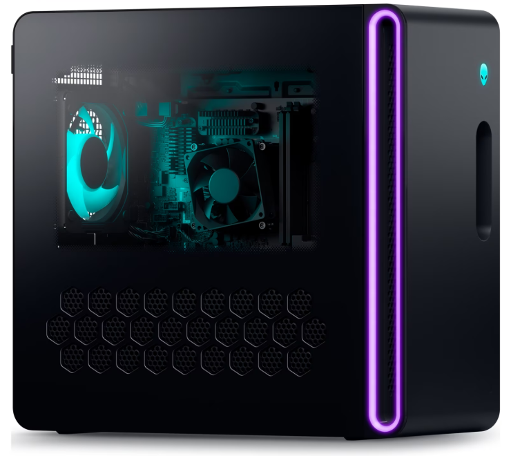
The Alienware Aurora ACT1250 Gaming PC is a high-performance desktop built for gamers and creators who demand powerful hardware combined with a striking design. Engineered with the latest Intel® Core™ Ultra processors and NVIDIA® GeForce RTX™ 40 and 50 series graphics cards, this system handles intensive gaming, streaming, and content creation seamlessly. Its modern chassis features optimized airflow and quieter acoustics, ensuring an immersive experience without distraction.
Designed for mainstream to enthusiast-level users, the Aurora ACT1250 offers flexible configurations, from a solid entry-level setup with an Intel Core Ultra 7 20-core CPU and RTX 4060 Ti GPU, to a top-tier powerhouse featuring a 24-core Intel Core Ultra 9 processor and RTX 5080 GPU. With up to 64GB DDR5 RAM and expansive NVMe SSD storage options, it delivers ultra-fast load times and smooth multitasking capabilities. The PC comes pre-installed with Windows 11 Home or Pro, catering to both gaming and professional environments.
Priced competitively between approximately $1,500 and $4,000, depending on configuration, the Alienware Aurora ACT1250 is widely available through Dell and authorized retailers. Its combination of robust specs, sleek aesthetics, and reliable performance makes it ideal for gamers, streamers, and digital artists seeking a future-proof desktop that balances speed, graphics fidelity, and upgrade potential.
Specifications of Alienware Aurora ACT1250
Dimensions and weight
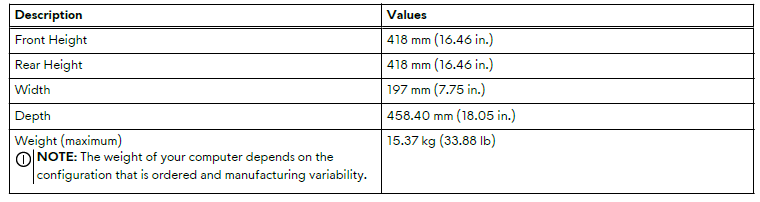
The following table lists the height, width, depth, and weight of your Alienware Aurora ACT1250.
Table 2. Dimensions and weight
Processor
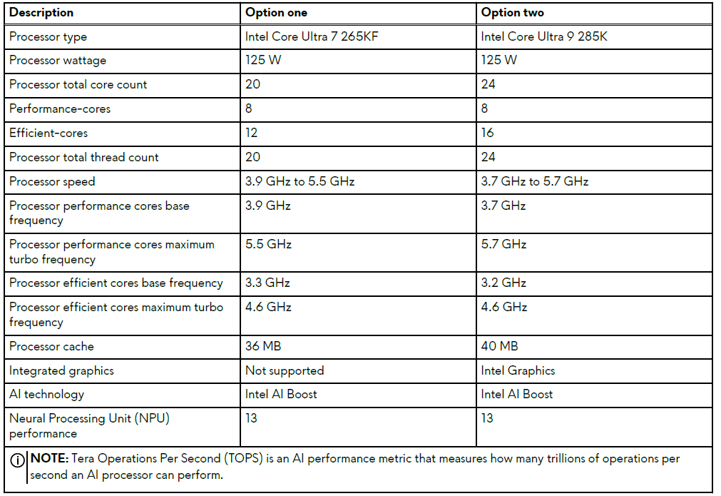
The following table lists the details of the processors that are supported on your Alienware Aurora ACT1250.
Table 3. Processor
Chipset
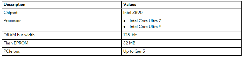
The following table lists the details of the chipset that is supported on your Alienware Aurora ACT1250.
Table 4. Chipset
Operating system
Your Alienware Aurora ACT1250 supports the following operating systems:
- Windows 11 Home
- Windows 11 Pro
Memory
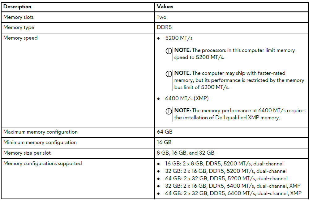
The following table lists the memory specifications that are supported on your Alienware Aurora ACT1250.
Table 5. Memory specifications
Ports and connectors
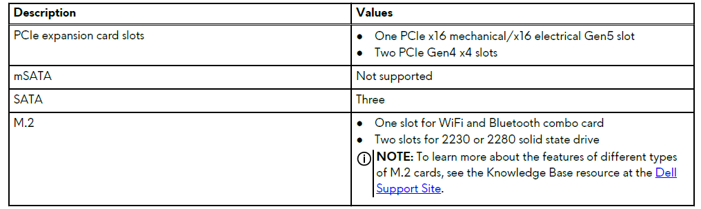
The following table lists the external and internal ports available on your Alienware Aurora ACT1250.
Table 6. External ports and connectors
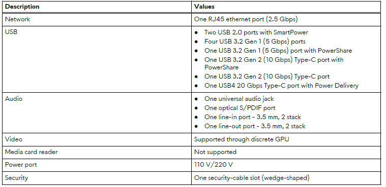
Table 7. Internal ports and connectors
Wireless module
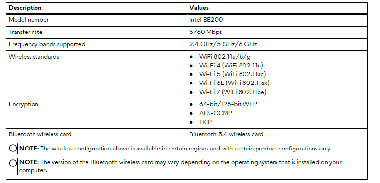
The following table lists the Wireless Local Area Network (WLAN) module specifications on your Alienware Aurora ACT1250.
Table 9. Wireless module specifications
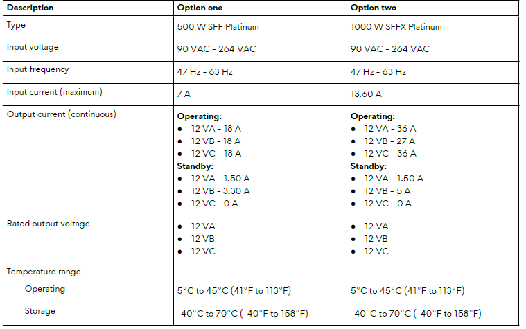
Power ratings
The following table lists the power rating specifications on your Alienware Aurora ACT1250.
Table 12. Power ratings
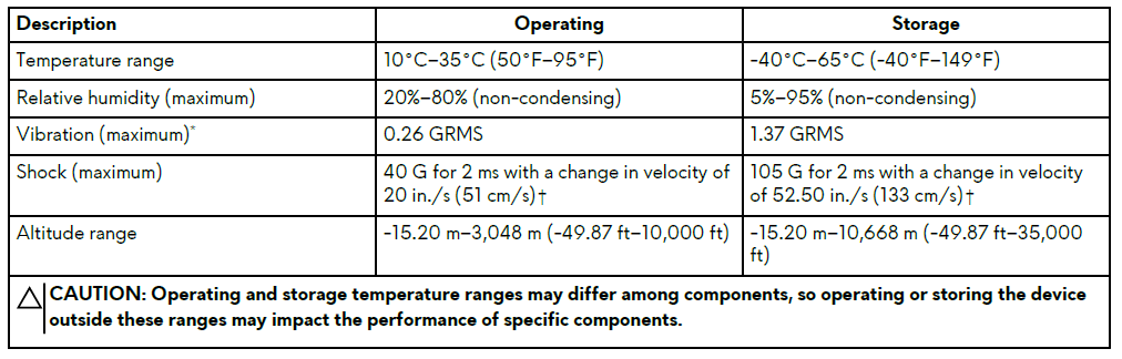
Operating and storage environment
The following table lists the operating and storage specifications of your Alienware Aurora ACT1250. Airborne contaminant level: G1 as defined by ISA-S71.04-1985
Table 18. Operating and storage environment
Views of Alienware Aurora ACT1250
Front
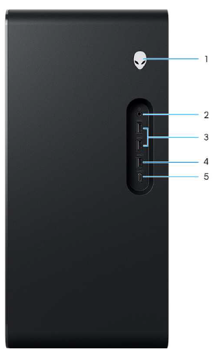
Figure 1. Front view
- Power button (Alien head)
Press to turn on the computer when the computer is turned off, in sleep state, or in hibernate state.
When the computer is turned on, press the power button to put the computer into a sleep state. Press and hold the power button for 10 seconds to force shut down the computer.
NOTE: The power-button behavior can be customized in the operating system. - Universal audio jack
Connect headphones or a headset (headphone and microphone combo). - USB 3.2 Gen 1 (5 Gbps) ports (2)
Connect devices such as external storage devices and printers. This port provides data transfer speeds up to 5 Gbps. - USB 3.2 Gen 1 (5 Gbps) port with PowerShare
Connect devices such as external storage devices and printers.
Supports data transfer speeds up to 5 Gbps. PowerShare enables you to charge your USB devices even when your computer is turned off.
NOTE: If your computer is turned off or in hibernation state, you must connect the power adapter to charge your devices using the PowerShare port. You must enable this feature in the BIOS setup program.
NOTE: Certain USB devices may not charge when the computer is turned off or in sleep state. In such cases, turn on the computer to charge the device. - USB 3.2 Gen 2 (10 Gbps) Type-C port with PowerShare
Connect devices such as external storage devices and printers.
The port provides data transfer speeds up to 10 Gbps. Supports Power Delivery that enables a two-way power supply between devices. Supports up to 15 W power output that enables faster charging.
NOTE: PowerShare enables you to charge your USB devices even when your computer is turned off.
NOTE: If the charge on your computer's battery is less than 10 percent, you must connect the power adapter to charge your computer, and USB devices connected to the PowerShare port.
NOTE: If a USB device is connected to the PowerShare port before the computer is turned off or in hibernate state, you must disconnect and reconnect it again to enable charging.
Back
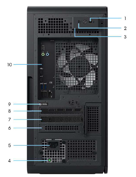
Figure 2. Back view
- Security-cable slot (for Kensington locks)
Connect a security cable to prevent unauthorized movement of your computer. - Padlock rings
Attach a standard padlock to prevent unauthorized access to the interior of your computer. - Side panel release latch
Release to allow opening the side panel. - Power-supply diagnostics light
The power-supply diagnostics light indicates the power-supply state. - Power-adapter port
Connect a power cable to provide power to your computer. - PCI-Express x4 slot
Connect a PCI-Express card,, such as audio, network, or expansion ca,, rd to enhance the capabilities of your computer. - PCI-Express x4 slot
Connect a PCI-Express card,, such as audio, network, or expansion card,,d to enhance the capabilities of your computer. - PCI-Express x16
Connect a PCI-Express graphics card for optimal graphics performance. - Service Tag label
The Service Tag is a unique alphanumeric identifier that enables Dell service technicians to identify the hardware components in your computer and access warranty information. - Back panel
Connect USB, audio, video, and other devices.
Back panel
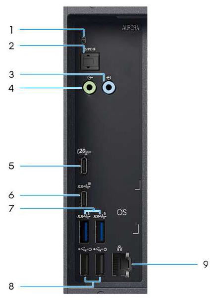
Figure 3. Back panel view
- Hard-drive activity light
The activity light turns on when the computer reads from or writes to the hard drive. - Optical S/PDIF port
Connect an amplifier, speakers, or a TV for digital audio output through an optical cable. - Line-in port
Connect recording or playback device,,s such as a microphone or CD player. - Line-out port
Connect audio-output devices such as speakers and amplifiers. In a 2.1 speaker channel setup, connect the left and right speakers. In a 5.1 or a 7.1 speaker channel setup, connect the front-left and front-right speakers. - USB4 20 Gbps Type-C port with Power Delivery
Supports data transfer only at rates of up to 20 Gbps for USB4. Supports Power Delivery that enables s a two-way power supply between devices. This port is not enabled for video capability.
NOTE: USB4 is backward compatible with USB 3.2, USB 2.0, and Thunderbolt 3. - USB 3.2 Gen 2 (10 Gbps) Type-C port
Connect devices such as external storage devices and printers. This port provides data transfer speeds up to 10 Gbps. - USB 3.2 Gen 1 (5 Gbps) ports (2)
Connect devices such as external storage devices and printers. This port provides data transfer speeds up to 5 Gbps. - USB 2.0 (480 Mbps) ports with Smart Power On (2)
Connect devices such as external storage devices and printers. This port provides data transfer speeds up to 480 Mbps.
NOTE: Deep Sleep is enabled by default. Disable Deep Sleep in the BIOS setup to enable the Smart Power On feature on your computer.
NOTE: Smart Power On is the ability to wake a computer from S0ix, S4, and S5 sleep states with a move of a mouse or a press of a key on the keyboard.
NOTE: This port does not support video or audio streaming or power delivery. - RJ45 Ethernet port (2.5 Gbps)
Connect an Ethernet (RJ45) cable from a router or a broadband modem for network or Internet access. The two lights next to the connector indicate the connectivity status and network activity.
Major components of Alienware Aurora ACT1250
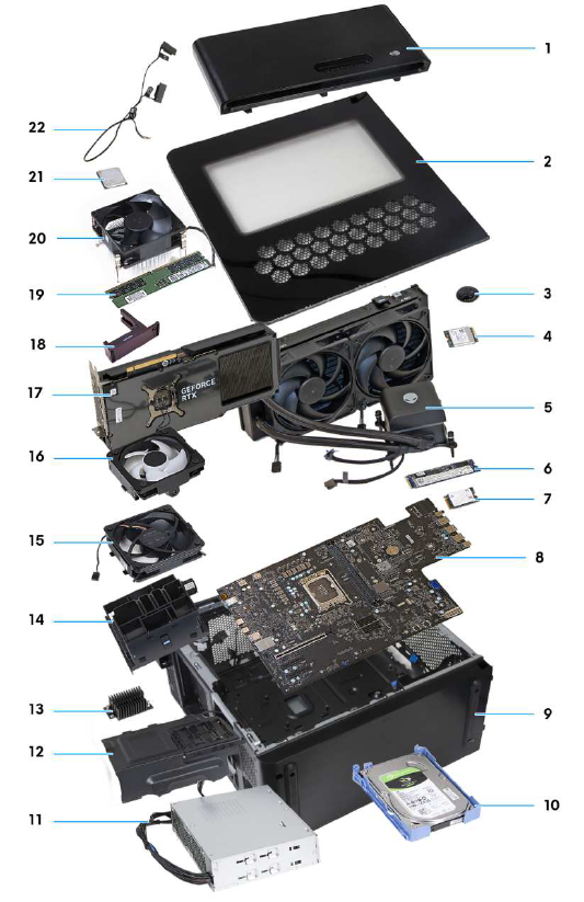
Figure 12. Major components of Alienware Aurora ACT1250
- Front bezel
- Left-side cover
- Coin-cell battery
- Wireless card
- Liquid-cooling assembly
- M.2 2280 solid state drive
- M.2 2230 solid state drive
- System board
- Chassis
- 3.5-inch hard drive
- Power-supply unit
- Power-supply unit bracket
- VR heat sink
- Graphics-card end holder
- Lower front-chassis fan
- Rear-chassis fan
- Graphics card
- Graphics-card bracket
- Memory module
- Processor fan and heat-sink assembly
- Processor
- Antenna
System-board components
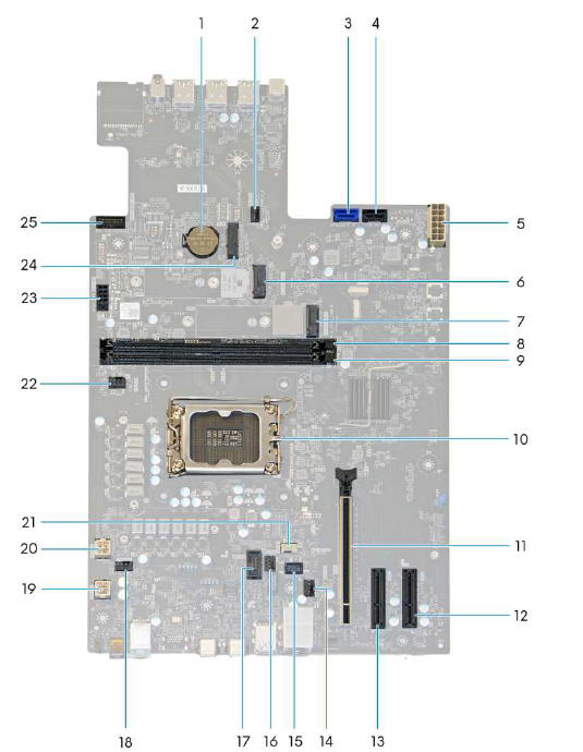
Figure 13. System-board components
- Coin-cell battery
- Lower front-chassis fan connector (FAN_SYS2)
- SATA 6 Gbps drive connector (SATA-0)
- SATA 6 Gbps drive connector (SATA-1)
- Power-supply connector (ATX SYS)
- Solid state drive slot (M.2 PCIe SSD-1)
- Solid state drive slot (M.2 PCIe SSD-0)
- Memory-module slot (DIMM1)
- Memory-module slot (DIMM2)
- CPU socket (CPU SKT1 COOLER)
- PCI-Express x16 mechanical/x16 electrical slot (SLOT1)
- PCI-Express x4 slot (SLOT3)
- PCI-Express x4 slot (SLOT2)
- Rear-chassis fan connector (FAN SYS1)
- Rear-chassis fan LED connector (LED FAN SYS1)
- Liquid cooling pump fan connector (FAN PUMP)
- Liquid-cooling pump LED connector (LED PUMP)
- Top-chassis fan connector one (FAN SYS4)
- Power-supply connector (ATX CPU2)
- Power-supply connector (ATX CPU1)
- Air-cooling fan connector (FAN CPU)
- Top-chassis fan connector two (FAN SYS5)
- SATA power connector (SATA PWR)
- Wireless-card slot (M.2 WLAN)
- Front I/O-panel cable (RING AMBIENT PWBT)
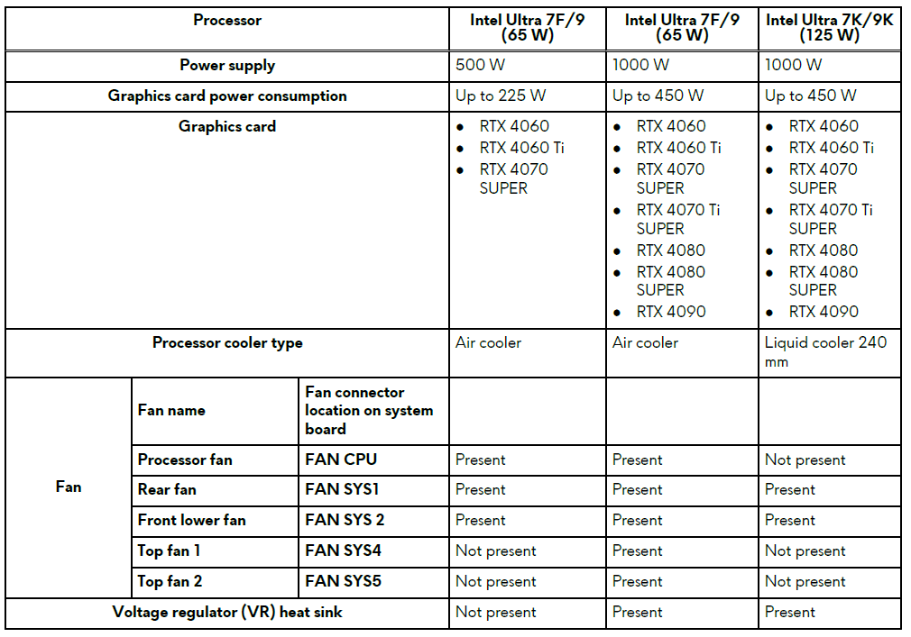
Thermal solution matrix
Table 20. Thermal solution matrix
Installing the left-side cover
Prerequisites
If you are replacing a component, remove the existing component before performing the installation procedure.
About this task
The following images indicate the location of the left-side cover and provide a visual representation of the installation procedure.
NOTE: The clear left-side cover is shipped with some computers.
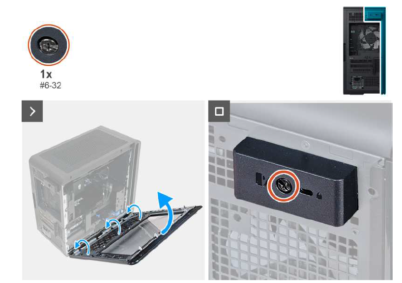
Figure 15. Installing the left-side cover
Steps
- Locate the tabs on the left-side cover and slots on the chassis.
- Rotate the left-side cover towards the chassis until it snaps into place.
- Tighten the captive screw (#6-32) that secures the side-cover release latch to the chassis.
Next steps
Follow the procedure after working on your computer.
Right-side cover
Removing the right-side cover
Prerequisites
- Follow the procedure in Before working inside your computer.
- Remove the left-side cover.
About this task
The following images indicate the location of the right-side cover and provide a visual representation of the removal procedure.
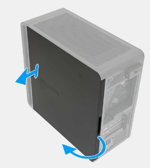
Figure 16. Removing the right-side cover
Steps
Pull and lift the right-side cover away from the chassis.
Installing the right-side cover
Prerequisites
If you are replacing a component, remove the existing component before performing the installation procedure.
About this task
The following images indicate the location of the right-side cover and provide a visual representation of the installation procedure.
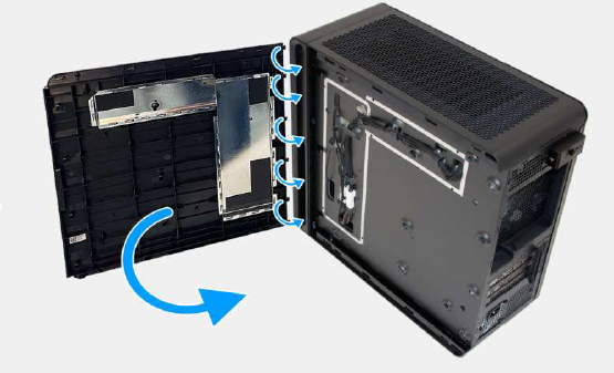
Set up your computer..
About this task
NOTE: The images in this document may differ from your computer depending on the configuration you ordered.
Steps
Connect the wired keyboard and mouse to the available ports. To connect a wireless keyboard and mouse, see the instructions on how to connect in the documentation that ships with the wireless keyboard and mouse.
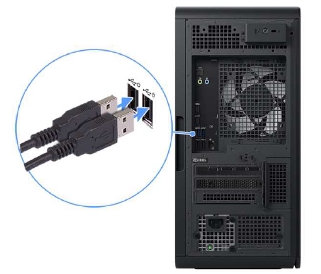
Figure 7. Connecting the wired keyboard and mouse
Connect to your network using an Ethernet cable.
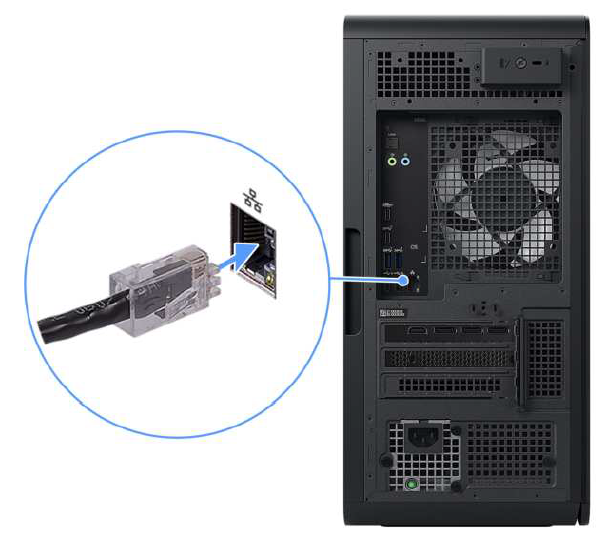
Figure 8. Connecting the Ethernet cable
Connect the display. For more information about setting up the display, see the documentation that is shipped with your display.
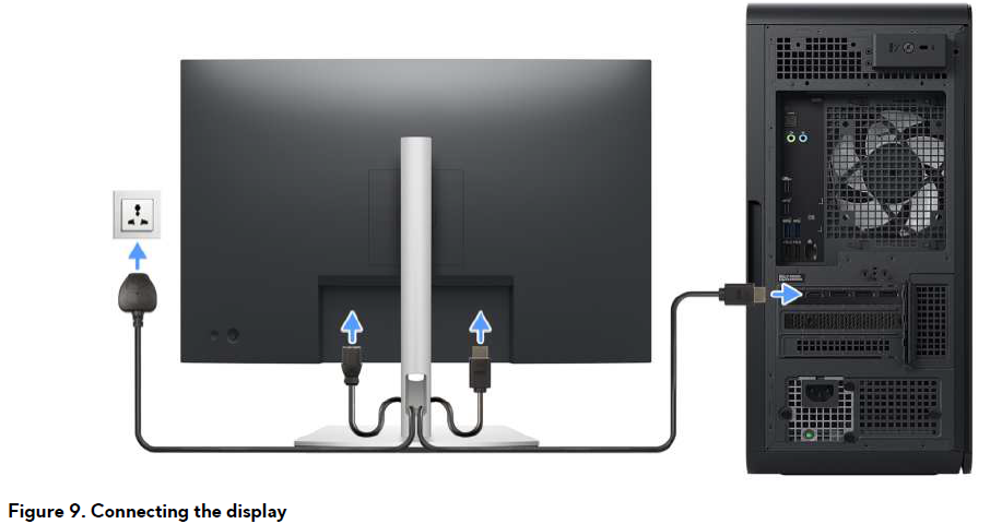
Figure 9. Connecting the display
Connect the power cable to the computer and then connect it to the wall outlet.
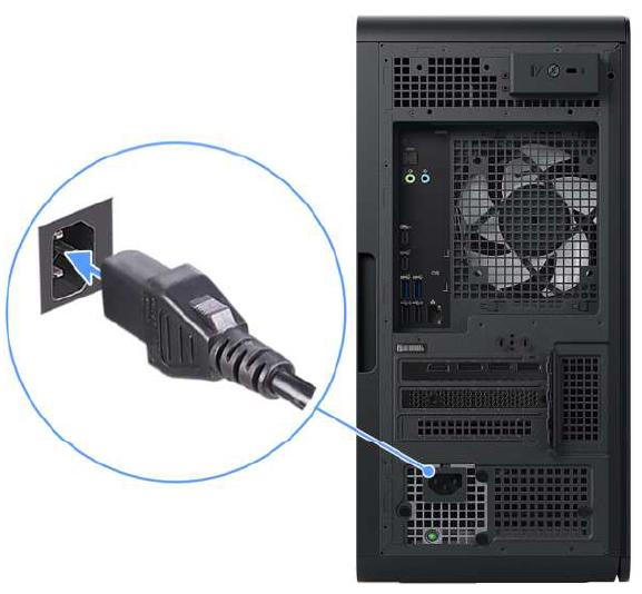
Figure 10. Connecting the power cable
Press the power button at the front of the computer to turn it on the computer.
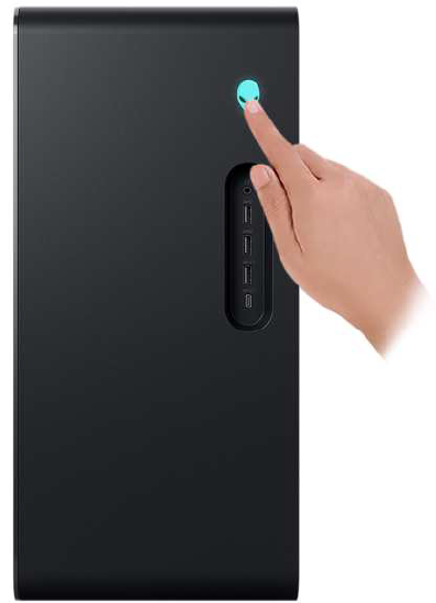
Figure 11. Pressing the power button
Safety precautions
This section details the primary steps to be followed before performing any disassembly instructions.
Observe the following safety precautions before you perform any installation or break-fix procedures involving disassembly or reassembly:
- Turn off the computer and all attached peripherals.
- Disconnect the computer from AC power.
- Disconnect all network cables and peripherals from the computer.
- Use an ESD field service kit when working inside any area to avoid electrostatic discharge (ESD) damage.
- Place the removed component on an anti-static mat after removing it from the computer.
- Wear shoes with nonconductive rubber soles to reduce the chance of getting electrocuted.
- Unplugging, pressing, and holding the power button for 15 seconds should discharge residual power in the system board.
Troubleshooting
Dell SupportAssist Pre-boot System Performance Check diagnostics
About this task
SupportAssist diagnostics (also known as system diagnostics) performs a complete check of your hardware. The Dell SupportAssist Pre-boot System Performance Check diagnostics are embedded within the BIOS and launched by the BIOS internally. The embedded system diagnostics provides options for particular devices or device groups,, allowing you to:
- Run tests automatically or in an interactive mode.
- Repeat the tests.
- Display or save test results.
- Run thorough tests to add more options and obtain details about any failed devices.
- View status messages that inform you when the tests are completed successfully.
- View error messages that inform you of problems encountered during testing.
NOTE: Some tests for specific devices require user interaction. Always ensure that you are present at the computer when the diagnostic tests are performed.
For more information, see the knowledge base article 000181163.
Running the SupportAssist Pre-Boot System Performance Check
Steps
- Turn on your computer.
- As the computer boots, press the F12 key.
- On the boot menu screen, select Diagnostics. The diagnostic quick test begins.
NOTE: For more information about running the SupportAssist Pre-Boot System Performance Check on a specific device, see the Dell Support Site. - If there are any issues, error codes are displayed.
Note the error code and validation number and contact Dell.
System-diagnostic lights
The power-status light indicates the power status of the computer. These are the power states:
- Solid white—Computer is in S0 state. This is the normal power state of the computer.
- Blinking white—Computer is in a low-power state, S3. This does not indicate a fault.
- Solid amber—The Computer is experiencing a boot failure, including the power-supply unit.
- Blinking amber—Computer is experiencing a boot failure,, but the power-supply unit is functioning correctly.
- Off—Computer is in hibernation mode or turned off.
The power-status light may also blink amber or white according to predefined "beep codes" indicating various failures.
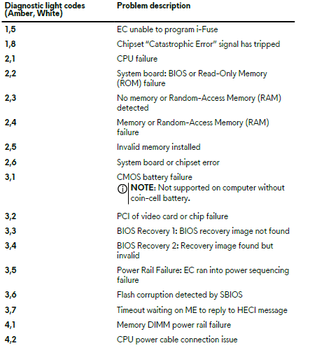
For example, the power and battery-status light blinks amber two times,, followed by a pause, and then blinks white three times,, es followed by a pause. This 2,3 pattern continues until the computer is turned off, indicating no memory or RAM is detected.
The following table shows different power and battery-status light patterns and associated problems.
Table 42. Diagnostic light codes
Pros & Cons of the Alienware Aurora ACT1250 Gaming PC
Pros
- Powerful Performance: Equipped with up to 24-core Intel Core Ultra 9 processors and NVIDIA RTX 5080 GPUs, it delivers exceptional gaming and creative workloads with ease.
- Modern Cooling & Acoustics: Features a 240mm AIO liquid cooler in higher-end models and optimized airflow, maintaining lower noise levels during intensive use.
- High-Speed Memory & Storage: Supports up to 64GB DDR5 RAM and multiple NVMe SSDs (up to 8TB), enabling fast multitasking and rapid game load times.
- Customizable Configurations: Multiple GPU and CPU options allow buyers to tailor performance based on budget and needs.
- Sleek Design & Build Quality: The chassis includes a clear side panel in premium editions, combining aesthetics with practical hardware cooling.
Cons
- Limited Internal Upgradeability: Some users report difficulty upgrading components post-purchase due to the compact and integrated design.
- Price Premium: Compared to some custom-built alternatives, Alienware’s brand and design add to the cost, which may impact value for budget-conscious gamers.
- Fan Noise Under Load: Though improved, certain configurations may produce noticeable fan noise during intense gaming sessions.
- Pre-installed Bloatware: Some users find the default software suite less streamlined, which could require manual cleanup for optimal performance.
Compared with alternatives like CyberPowerPC or custom DIY builds, the Alienware Aurora ACT1250 trades off upgrade flexibility and price for a polished out-of-the-box experience and Dell’s reputable support.
Customer Reviews of the Alienware Aurora ACT1250 Gaming PC
Users consistently praise the Alienware Aurora ACT1250 Gaming PC for its robust gaming performance and smooth multitasking capabilities. Many highlight the powerful Intel Core Ultra 7 and RTX 50 series GPU combination for delivering high frame rates and impressive graphics quality in AAA titles. The system's sleek design and efficient cooling have also been commended, with multiple reviewers noting quieter operation compared to previous Alienware generations.
Average star ratings hover around 4 to 4.5 out of 5, reflecting strong overall satisfaction. Testimonials frequently note fast boot and load times thanks to the NVMe SSD and ample DDR5 memory, enabling seamless content creation workflows alongside gaming.
Common complaints include fan noise during peak load and some initial software setup complexities. A few users mention limited upgrade options internally, advising prospective buyers to carefully select their desired specs upfront. Despite these issues, most recommend the PC for gamers and professionals seeking a reliable, high-end desktop with solid value. Purchase recommendations emphasize considering configuration choices based on intended use and budget.
Faqs
How do I set up the alienware Aurora ACT1250 Gaming PC for the first time?
What should I do if my alienware Aurora ACT1250 Gaming PC is not working properly?
Can I use the alienware Aurora ACT1250 Gaming PC with a 4K monitor?
How often should I maintain the alienware Aurora ACT1250 Gaming PC?
What are the key features that make the alienware Aurora ACT1250 Gaming PC different?
Can I upgrade the RAM in the alienware Aurora ACT1250 Gaming PC?
How do I optimize the alienware Aurora ACT1250 Gaming PC for better performance?
What are the compatibility requirements for using the alienware Aurora ACT1250 Gaming PC with external devices?
Tags
More alienware manuals
Leave a Comment