
Hp Procurve Switch 2124 Instruction Manual | Specifications
Content
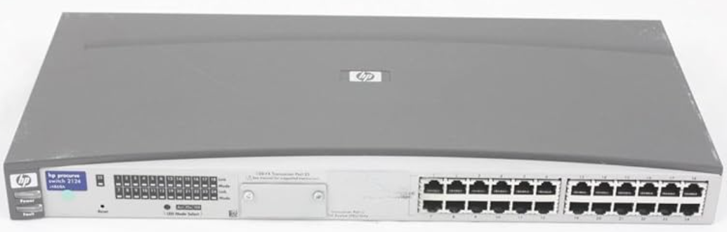
HP ProCurve Switch 2124
Introduction
The HP ProCurve Switch 2124 is a high-performance network switch designed for small to medium-sized businesses. It offers reliable and secure connectivity for your network infrastructure.
Specifications
Physical
- Width:
- 44.2 cm (17.4 in)
- Depth:
- 20.5 cm (8.1 in)
- Height:
- 4.4 cm (1.7 in)
- Weight:
- 2.5 kg (5.5 lbs)
Electrical
The switch automatically adjusts to any voltage between 100-240 volts and either 50 or 60 Hz.
- AC voltage:
- 100-240 volts
- Maximum current:
- 1.0 A
- Frequency range:
- 50/60 Hz
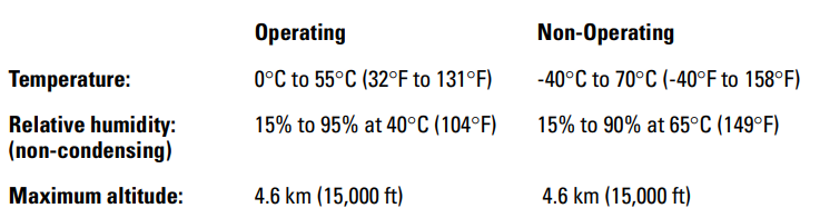
Environmental
Instructions
- Connect the power cord to the switch and plug it into a power outlet.
- Connect your devices to the switch using Ethernet cables.
- Configure the switch using the web-based management interface or the command-line interface.
- Monitor and manage your network using the provided software tools.
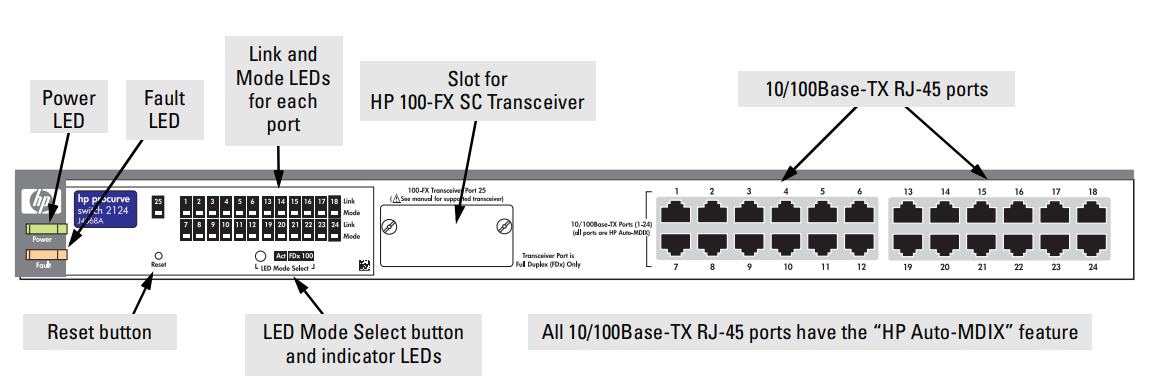
Front of the Switch
Network Ports
- 24 auto-sensing 10/100Base-TX RJ-45 ports
- All these ports have the “HP Auto-MDIX” feature, which means that you can use either straight-through or crossover twisted-pair cables to connect any network devices to the switch.
- One transceiver slot for installing the HP 100-FX SC Transceiver (HP J4853A)
Reset Button
This button is used to reset the switch while it is powered on. This action executes the switch self-test, and may clear certain error conditions that have occurred.
Back of the Switch
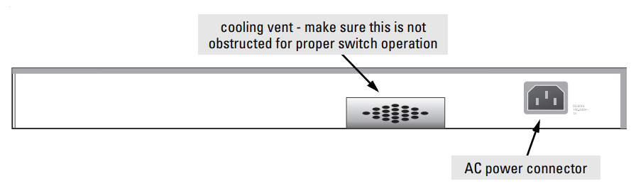
Power Connector
The Switch 2124 does not have a power switch; it is powered on when connected to an active AC power source. The switch automatically adjusts to any voltage between 100--240 volts and either 50 or 60 Hz. There are no voltage range settings required.
Features
The features of the Switch 2124 include:
- 24 auto-sensing 10/100Base-TX RJ-45 ports with “HP Auto-MDIX”
- a slot for installing an HP 100-FX SC Transceiver (HP J4853A)
- Plug-and-play networking — all ports are enabled — just connect the network cables to active network devices and your switched network is operational.
- “HP Auto-MDIX” on all 10/100 twisted-pair ports, meaning that all connections can be made using straight-through twisted-pair cables. Cross-over cables are not required, although they will also work. The pin operation of each port is automatically adjusted for the attached device: if the switch detects that another switch or hub is connected to the port, it configures the port as MDI; if the switch detects that an end-node device is connected to the port, it configures the port as MDI-X.
- automatic learning of the hardware addresses in the switch’s 4000-entry address forwarding table
- automatically negotiated full-duplex operation for the fixed 10/100 RJ-45 ports when connected to other auto-negotiating devices — the transceiver port always operates at full duplex.
- auto-negotiation of flow control for ports operating at full duplex
Switch Operation Overview
Address Table Operation
Address Learning. As devices are connected to the switch ports, either directly or through hubs or other switches that are connected to the switch, the MAC addresses of those devices are learned automatically and stored in the Switch 2124’s 4000-entry address table. The switch also identifies the number of the port on which each address is learned, so it knows the relative network location of each device.
Forwarding, Filtering, Flooding. When the switch receives a packet, it determines the destination address, and looks for the address in the address table. Based on the port location of that address, the switch then determines whether to forward, filter out, or flood the packet.
- Forward - if the destination address is on a different port than the one on which the packet was received, the packet is forwarded to the destination port and on to the destination device.
- Filter out - if the destination address is on the same port as the one on which the packet was received, the packet is filtered out. The switch thereby isolates local traffic, so the rest of the network connected to the switch does not use bandwidth dealing with unnecessary traffic. Floodd - whenever a new destination address is found in a packet received on a port, the destination address will not yet be in the switch’s address table,e and the Switch 2124 cannot know whether to forward or filter out the packet. In this case, it sends the packet to all the other switch ports. This is referred to as “flooding”. When the destination device receives the packet, it replies, and the switch learns the new address from the reply packet. Then, all future packets destined for that address are forwarded or filtered out appropriately.
Network Moves and Changes. When devices are moved in the network, and become connected to a different switch port, the Switch 2124 automatically recognizes the change and updates the address table with the new port location of the device. Communication with the device is automatically maintained without any address table manipulation being required.
Installing the Switch 2124
The HP Switch 2124 is easy to install. It comes with an accessory kit that includes the brackets for mounting the switch in a standard 19-inch telco rack or an equipment cabinet, or on a wall, and with rubber feet that can be attached so the switch can be securely located on a horizontal surface. The brackets are designed to allow mounting the switch in a variety of orientations.
This chapter shows you how to install your Switch 2124.
Included Parts
The Switch 2124 has the following components shipped with it:
- HP PrProCurvewitch 2124 Installation Guide (J4868-90001), this manual
- Customer Support/Warranty booklet
- Accessory kit (5064-2085), two mounting brackets
- Four 8 mm M4 screws to attach the mounting brackets to the switch
- Four 5/8-inch number 12-24 screws to attach the switch to a rack
- Four rubber feet
- Power cord, one of the following:
- Australia/New Zealand
- 8120-6803
- China
- 8120-8377
- Continental Europe
- 8120-6802
- Denmark
- 8120-6806
- Japan
- 8120-6804
- Switzerland
- 8120-6807
- United Kingdom/Hong Kong/Singapore
- 8120-8709
- United States/Canada/Mexico
- 8120-6805
- Australia/New Zealand
Installation Procedures
Summary
Follow these easy steps to install your switch. The rest of this chapter provides details on these steps.
- Prepare the installation site. Make sure that the physical environment into which you will be installing the switch is properly prepared, including having the correct network cabling ready to connect to the switch, and having a good location for the switch. Please see pages 2-3 for some installation precautions.
- (Optional) Install the transceiver. The Switch 2124 has a slot for installing an HP 100-FX SC Transceiver (HP J4853A). Depending on where you will locate the Switch 2124, it may be easier to install the transceiver first.
- Verify that the switch passes the itself-test. This is a simple process of plugging the switch into a power source and observing that the LEDs on the switch’s front panel show correct operation. See pages 2-7.
- Mount the switch. The Switch 2124 can be mounted in a 19-inch telco rack or equipment cabinet, on a wall, or on a horizontal surface.
- Connect power to the switch. Once the switch is mounted, plug it into the nearby AC power source.
- Connect the network devices. Using the appropriate network cables, connect computers, printers, servers, hubs, other switches, routers, and other network devices to the switch ports.
At this point, the switch is fully installed,, and your network should be up and running. See the rest of this chapter if you need more detailed information on any of these installation steps.
Installation Precautions:
Follow these precautions when installing your HP Switch 2124.
- The rack or cabinet should be adequately secured to prevent it from becoming unstable and/or falling over.
- Devices installed in a rack or cabinet should be mounted as low as possible, with the heaviest device at the bottom and progressively lighter devices installed above.
- Make sure that the power source circuits are properly grounded, then use the power cord supplied with the switch to connect it to the power source.
- If your installation requires a different power cord than the one supplied with the switch, be sure the cord is adequately sized for the switch’s current requirements. In addition, be sure to use a power cord displaying the mark of the safety agency that defines the regulations for power cords in your country. The mark is your assurance that the power cord can be used safely with the switch.
- When installing the switch, note that the AC outlet should be near the switch and should be easily accessible in case the switch must be powered off.
- Ensure that the switch does not overload the power circuits, wiring, and over-current protection. To determine the possibility of overloading the supply circuits, add together the ampere ratings of all devices installed on the same circuit as the switch and compare the total with the rating limit for the circuit. The maximum ampere ratings are usually printed on the devices near the AC power connectors.
- Do not install the switch in an environment where the operating ambient temperature might exceed 55 °C (131°F).
- Make sure the air flow around the sides and back of the switch is
not restricted. - Make sure that if no transceiver is installed in the transceiver slot, the cover plate is installed to cover the slot. A cover plate is required for safe operation, and to ensure proper switch cooling.
Prepare the Installation Site
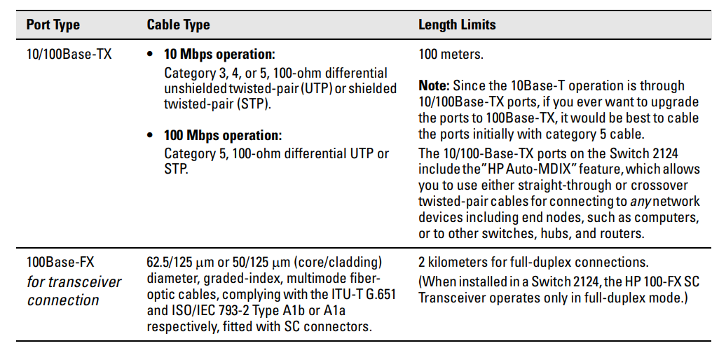
Cabling Infrastructure - Ensure that the cabling infrastructure meets the necessary network specifications. See the following table for cable types and lengths, and see Appendix B, “Switch Ports and Network Cables,,” for more information:
Table 2-1. Summary of Cable Types to Use with the Switch
Installation Location - Before installing the switch, plan its location and orientation relative to other devices and equipment:
- At the front of the switch, leave at least 7.6 cm (3 inches) of space for the twisted-pair and fiber-optic cabling.
- At the back of the switch, leave at least 7.6 cm (3 inches) of space for the power cord and cooling.
- On the sides of the switch, leave at least 3.8 cm (1 1/2 inches) for cooling.
Install An Optional Transceiver
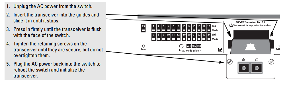
Install an optional HP 100-FX SC Transceiver into the transceiver slot as shown in the illustration below, or by following the instructions in the manual that comes with the transceiver.
The slot cover can be removed with either a flat-bladed or Torx T-1screwdriverscrewdriverer. Retain the slot cover for future use.
- Install only the HP J4853A 100-FX SC Transceiver into the transceiver slot in the Switch 2124.
- Make sure the transceiver is fully installed and that you screw in the retaining screws to secure the transceiver in place.
- If you do not install a transceiver in the slot, make sure that the slot cover plate is still attached over the slot for safe operation and proper switch cooling.
- In the Switch 2124, the transceiver can operate only at full duplex. Half-duplex operation is not supported.
Installing a Transceiver
Verify the Switch Operates Correctly
After you have optionally installed a transceiver, but before mounting the switch in its network location, you should first check that it is working properly by plugging it into a power source and verifying that it passes its self-test.
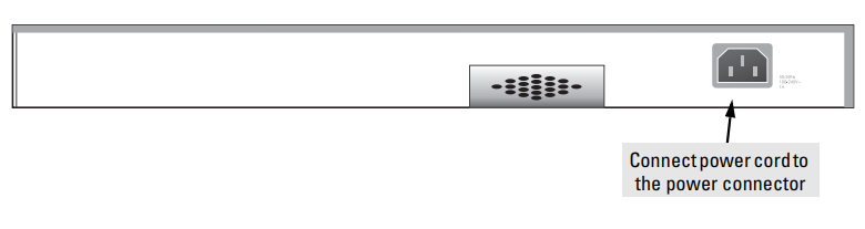
- Connect the power cord supplied with the switch to the power connector on the back of the switch, and then into a nearby properly grounded electrical outlet.
- The Switch 2124 does not have a power switch. It is powered on when the power cord is connected to the switch and to a power source. For safety, the power outlet should be located near the switch installation.
- The switch automatically adjusts to any voltage between 100-240 volts and either 50 or 60 Hz. There are no voltage range settings required.
- If your switch requires a different power cord than the one supplied with the switch, please see the Installation Precautions on pages 2- 3.
- Check the LEDs on the switch. The LED behavior is described on the next page.
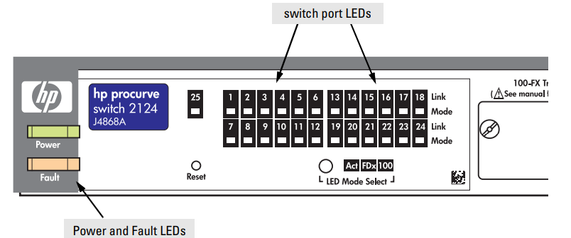
When the switch is powered on, it performs its diagnostic self-test. The self-test takes approximately 3 seconds to complete.
LED Behavior:
During the self-test:
- All the switch and port LEDs are on.
When the self-test completes successfully:
- The large Power LED remains on.
- The large Fault LED goes off.
- The LED Mode Select Act remains on.
- The port LEDs (Link and Mode) go into their normal operational mode:
- If the ports are connected to active network devices, the Link LEDs stay on and the Mode LEDs behave according to the mode selected. In the default mode (Activity), the Mode LEDs should flicker, showing network activity on the port.
- If the ports are not connected to active network devices, the Link and Mode LEDs will stay off.
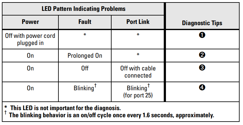
- If the LED display is different than what is described above, especially if the Fault LED stays on for more than 10 seconds or it starts blinking, the self-test has not completed correctly. Refer to chapter 3, “Troubleshooting” for diagnostic help.
Mount the Switch
After a transceiver has been installed and you have verified that the switch passes its self-test, you are ready to mount the switch in a stable location. The Switch 2124 can be mounted in these ways:
- in a rack or cabinet
- on a horizontal surface
- on a wall
Rack or Cabinet Mounting
- The Switch 2124 is designed to be mounted in any EIA-standard 19-inch telco rack or in an equipment cabinet such as a server cabinet.
- For safe operation, please read the Installation Precautions on pages 2-3 before mounting the switch.
- If you are installing the switch in an equipment cabinet, use the clips and screws that came with the cabinet in place of the 12-24 screws that are supplied with the switch. Plan which four holes you will be using in the cabinet and install all four clips and partially install the two bottom screws, as described in step 2 on the next page. Then proceed to step 3.
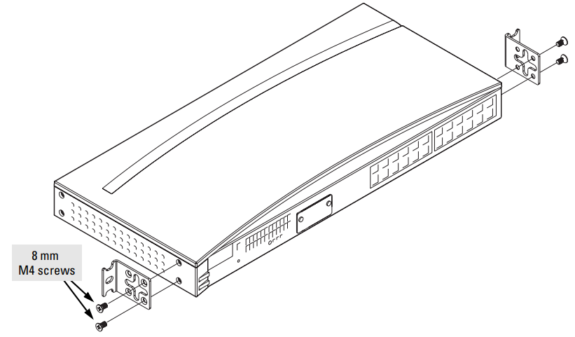
Use a #1 Phillips (cross-head) screwdriver and attach the mounting brackets to the switch with the included 8-mm M4 screws . Steps 2, 3, and 4 below describe a convenient method of mounting the switch in a rack by placing it on two screws that you first install in the rack. You may, instead, just hold the switch with attached brackets up to the rack and move it vertically until rack holes line up with the bracket notches, then insert and tighten the four screws holding the brackets to the rack.
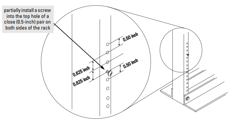
Partially install a screw (5/8-inch number 12-24) into the top hole of a pair of holes that are 0.5 inches apart in each rack/cabinet upright, ht as shown in the illustration below. Ensure that the screws are at the same level in each upright.
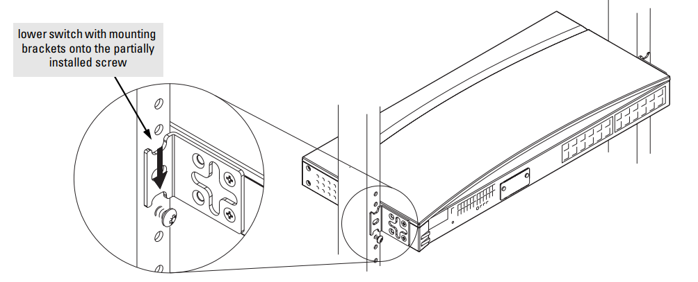
Place the switch in the rack and lower it so the notches in the bottom of the bracket slide onto the screws, then tighten these screws.
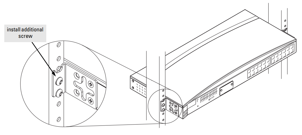
Install the other number 12-24 screw into the upper hole in each bracket. Tighten these screws.
Wall Mounting
- You can mount the switch on a wall as shown in the illustrations below.
The switch should be mounted only to a wall or wood surface that is at least 1/2-inch plywood or its equivalent.
- Use a #1 Phillips (cross-head) screwdriver and attach the mounting brackets to the switch with the included 8-mm M4 screws.
- Attach the switch to the wall or wood surface with 5/8-inch number 12 wood screws (not included).
Horizontal Surface Mounting
Place the switch on a table or other horizontal surface. The switch comes with rubber feet in the accessory kit that can be used to help keep the switch from sliding on the surface. Attach the rubber feet to the four corners on the bottom of the switch within the embossed angled lines. Use a sturdy surface in an uncluttered area. You may want to secure the networking cables and switch power cord to the table leg or other part of the surface structure to help prevent tripping over the cords.
Make sure the air flow is not restricted around the sides and back of the switch.
Basic Troubleshooting Tips
Most problems are caused by the following situations. Check for these items first when starting your troubleshooting:
- Connecting the RJ-45 ports to devices that have a fixed full-duplex configuration. The Switch 2124 RJ-45 ports are configured as “Auto”. That is, when connecting to attached devices, the switch will operate in one of two ways to determine the link speed and the communication mode (half duplex or full duplex):
- If the connected device is also configured to Auto, the switch will automatically negotiate both link speed and communication mode
- If the connected device has a fixed configuration, for example, 100 Mbps, at half or full duplex, the switch will automatically sense the link speed, but will default to a communication of half duple.x
- Because the Switch 2124 behaves in this way (in compliance with the IEEE 802.3 standard), if a device connected to the switch RJ-45 ports has a fixed configuration at full duplex, the device will not connect correctly to the switch. The result will be high error rates and very inefficient communications between the switch and the device.
- Make sure that all devices connected to the Switch 2124 RJ-45 ports are configured to auto-negotiate, or are configured to connect at half duplex (all hubs are configured this way, for example).
- Connecting the 100Base-FX transceiver port to other devices. An HP 100-FX SC Transceiver installed in the Switch 2124 operates only at 100 Mbps and full duplex. When connecting this port to any other device, make sure that the port on that device is configured the same. Otherwise, the communication over that link could have high error rates and could be very inefficient, or the link might not be established at all.
- Faulty or loose cables. Look for loose or obviously faulty connections. If they appear to be OK, make sure the connections are secure. If that does not correct the problem, try a different cable.
- Non-standard cables. Non-standard and miswired cables may cause network collisions and other network problems, and can seriously impair network performance. Use a new correctly-wired cable or compare your cable to the cable in Appendix B, “Switch Ports and Network Cables,” for pinouts and correct cable wiring. A category 5 cable tester is a recommended tool for every 100Base-TX network installation.
- Improper Network Topologies. It is important to make sure you have a valid network topology. Common topology faults include excessive cable length and excessive repeater delays between end nodes. If you have network problems after recent changes to the network, change back to the previous topology. If you no longer experience the problems, the new topology is probably at fault. Example topologies are shown at the end of Chapter 2 in this book, and some topology configuration guidelines can be found online at the HP ProCurve website, in the Information Library section.
- In addition, you should make sure that your network topology contains no data path loops. Between any two end nodes, there should be only one active cabling path at any time. Data path loops will cause broadcast storms that will severely impact your network performance.
Diagnosing with the LEDs
Table 3-1 shows LED patterns on the switch that indicate problem conditions.
- Check in the table for the LED pattern that you see on your switch.
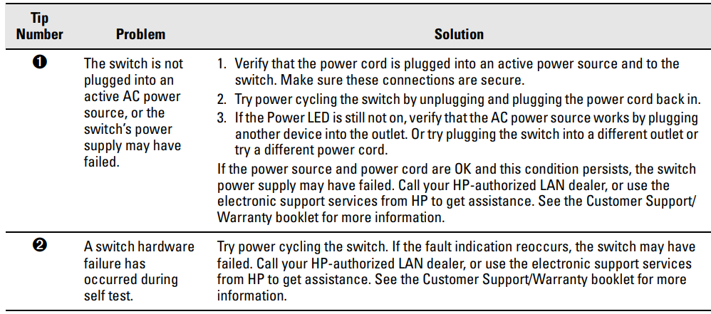
- Refer to the corresponding diagnostic tip on the next few pages.
Table 3-1. LED Error Indicators
Diagnostic Tips:
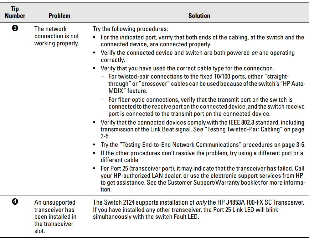
Hardware Diagnostic Tests
Testing the Switch by Resetting It
If you believe that the switch is not operating correctly, you can reset the switch to test its circuitry and operating code. To reset a switch, either:
- Unplug and plug in the power cord (power cycling)
- Press the reset button on the front of the switch
Power cycling the switch and pressing the Reset button both cause the switch to perform its power-on self-test, which could resolve any temporary operational problems.
Checking the Switch LEDs
The self-test passes if the Fault LED on the front of the switch goes off after approximately 3 seconds. If this LED stays on longer than 10 seconds or begins blinking, an error condition has been detected on the switch.
See “Diagnosing with the LEDs” on page 3-3 for information on interpreting the LED patterns.
Testing Twisted-Pair Cabling
Network cables that fail to provide a link or provide an unreliable link between the switch and the connected network device may not be compatible with the IEEE 802.3 10Base-T or 100Base-TX standards. The twisted-pair cables attached to the Switch 2124 must be compatible with the appropriate standards. To verify that your cable is compatible with these standards, use a qualified cable test device.
HP also offers a wire testing service. Contact your HP-authorized LAN dealer or your local HP sales office for more information.
Testing End-to-End Network Communications
Both the switch and the cabling can be tested by running an end-to-end communications test — a test that sends known data from one network device to another through the switch. For example, if you have two PCs on the network that have LAN adapters between which you can run a link-level test or a ping test through the switch, you can use this test to verify that the entire communication path between the two PCs is functioning correctly. See your LAN adapter documentation for more information on running a link test or a Ping test.
Faqs
Is the hp Procurve Switch 2124 suitable for PoE devices?
Can the switch be mounted in a rack?
What management interfaces are available?
Does the switch support VLANs?
What is the switching capacity of the switch?
Is the switch suitable for small to medium-sized businesses?
Can the switch prioritize certain types of network traffic?
What are the dimensions of the switch?
Does the switch come with software tools for network management?
What is the weight of the switch?
More hp manuals
- Set-up & Operations: Hp Pavilion PC User Guide
- Hp 10B Business Calculator Owner Manual | Functions & Usage
- Specifications & Connection: Hp DeskJet 1110 Series User Guide
- Hp Sprocket Printer User Manual | Specs & Features
- Settings & Connections: Hp x2 Detachable 10-p0XXHP PC User Guide
- Hp Laptop 17-cn0010nr User Guide | Specifications
Leave a Comment